
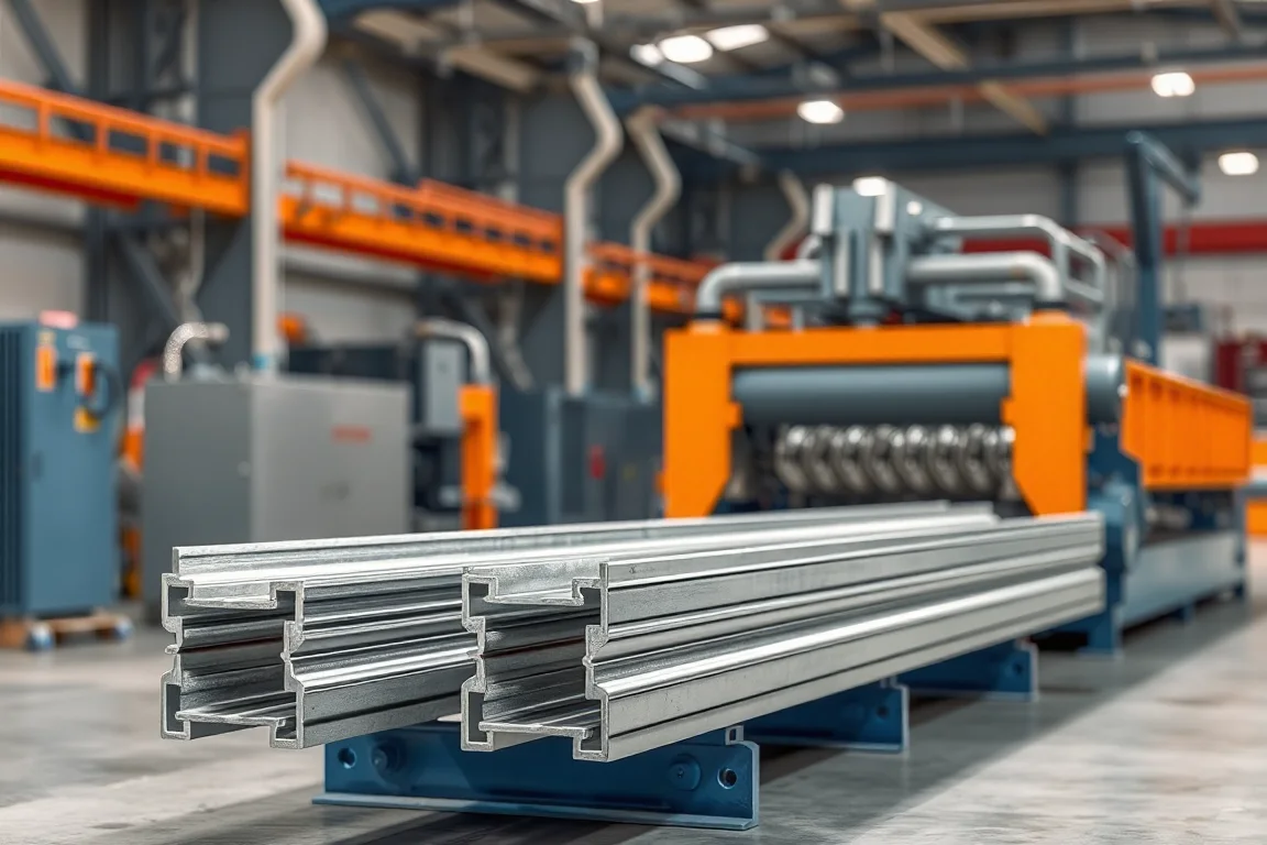
Solar mounting roll forming equipment serves defined components of a photovoltaic support system. Strut channels, module rails, brackets, purlins and posts have different interfaces and manufacturing requirements. A module's perimeter frame is also a different product from the rails that support it. Start by identifying the actual part rather than buying from a broad solar-machine label.
Locate the component within the mounting assembly
Show how the part connects to modules, clamps, brackets and the supporting structure. This identifies functional returns, slots and clearances that may be hidden in an outside view. A channel with a familiar outline can still fail to accept the intended fitting.
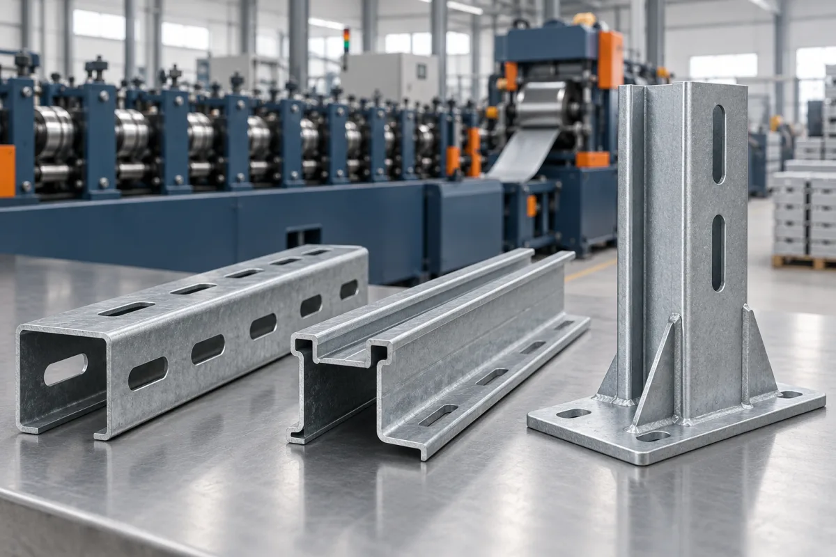
- Solar Strut: focus on the internal fitting interface and specified slot pattern.
- Mounting Rail: define the module-clamp and support connections.
- Panel Frame: review the actual perimeter construction and whether roll forming suits it.
- PV Bracket: identify the component geometry and any secondary fabrication.
Keep steel roll forming distinct from other processes
A product commonly supplied through another process is not automatically reproduced by a roll former. Use the actual material and section drawing to assess feasibility. Do not transfer assumptions from an aluminum extrusion directly to a proposed steel roll-formed part.
Constant sections, locally changing geometry, corner construction and additional holes can lead to different process routes. Identify which features are made continuously and which require cutting, pressing, joining or other operations afterward.
Specify fitting interfaces and feature references
Include internal openings, returns, clamp contact areas, slots and cut-end requirements. Use the selected nuts, clamps and brackets during approval. Matching an exterior width does not prove that a fitting can be inserted, positioned or secured as intended.
For a size family, show how the functional interfaces change or remain common. List the corresponding tools and feature programs. A width-adjustable channel line does not necessarily preserve every internal clearance without additional setup or parts.
Connect material and finishing to the component design
Specify grade or alloy, thickness and the required coating route. Environmental exposure and structural requirements belong to the mounting-system design. The machine is evaluated on producing the specified component, not on assigning a service life or load rating.
Inspect samples after the agreed manufacturing and finishing operations. Hole edges, tight returns and contact surfaces can require different checks. Keep the material and process identity with the trial results so later substitutions can be reviewed deliberately.
Demonstrate assembly and repeatable changeover
Trial complete samples with their intended fittings and connection components. Verify slot references, engagement and any necessary access. Avoid making local alterations to conceal a mismatch during a demonstration.
For recurring variants, measure the full transition through an accepted product and a satisfactory fit check. Include punch tools, guides, cutoff and inspection in addition to roll adjustments. Retain setup references by product drawing rather than relying on a generic solar-profile name.
Compare completed components over the actual order mix
Count accepted rails, channels or brackets with all required operations complete. Frequent slots, many project lengths and secondary work can influence output more than strip speed. Installed photovoltaic capacity is not a direct machine-output measure without a defined component schedule.
Prepare the part drawings, material matrix, fitting samples, finishing route and normal orders. The detailed pages in this category help separate component roles and build an equipment scope that matches the actual mounting product instead of an undefined solar-equipment package.
Continue your research
- Solar Strut Channel Roll Forming Machine
- Solar Mounting Rail Roll Forming Machine
- Solar Panel Frame Roll Forming Machine
- PV Bracket Roll Forming Machine
- Solar C Channel Roll Forming Machine
- Solar U Channel Roll Forming Machine
- Solar Hat Channel Roll Forming Machine
- Solar Purlin Roll Forming Machine
- Ground Mount Solar Post Roll Forming Machine
- How Solar roll forming machine Works
- How To Choose a Solar roll forming machine
- Solar roll forming machine Price: What Affects the Cost?
- Materials and Thickness for Solar roll forming machine
- Production Speed and Output of Solar roll forming machine
- Roller, Tooling and Forming Design for Solar roll forming machine
- Common Defects and Troubleshooting for Solar roll forming machine
- Maintenance Checklist for Solar roll forming machine