
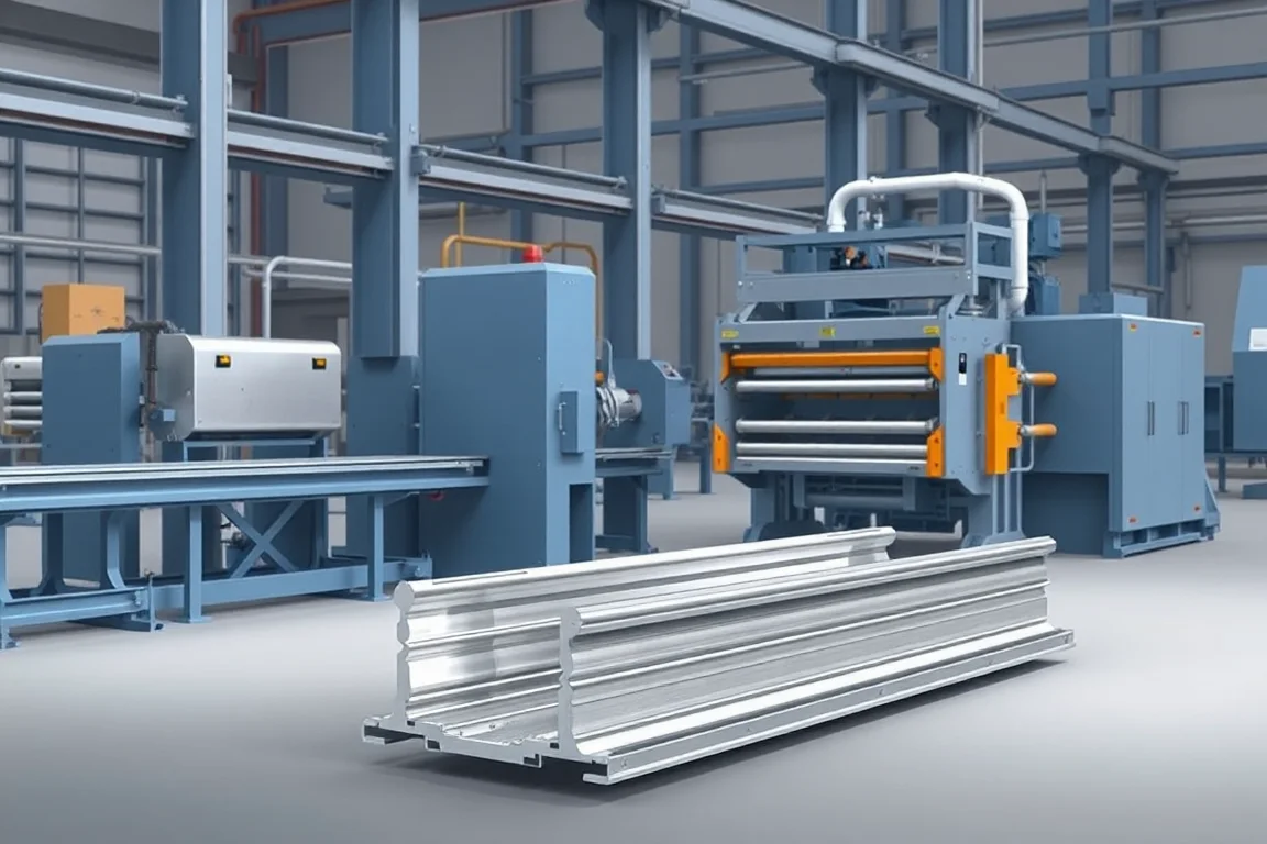
A solar panel frame roll forming machine is relevant when the perimeter frame of a photovoltaic module has been designed as a roll-formed metal construction. The equipment makes specified frame members whose module-seating surfaces, corners, fixing details and finish must work together in the completed frame.
This is not the same product as the mounting rails or support brackets beneath a module. It is also not a direct replacement for every extruded frame profile. The first step is to identify the actual frame design and confirm that its geometry and assembly method suit a sheet-forming process.
Which frame does the project mean?
Clarify whether the enquiry concerns the perimeter around the module laminate or the external structure that supports the module. The same informal phrase solar frame is sometimes used for both, but the interfaces and production routes are different.
For a module perimeter, the drawing should show the seating or retention relationship with the module construction, the mounting interfaces and the corner assembly. For a support structure, the project belongs to the separate rail, strut or bracket family. Resolving this distinction early prevents equipment being quoted for the wrong component.
When should roll forming be compared with extrusion?
Review the complete section, material and production volume. Roll forming develops bends in strip, while extrusion creates a section through a different material process. A familiar extruded frame may contain walls or cavities that cannot simply be recreated with ordinary roll passes.
A formed alternative may use a different section or joined construction. Such a change requires product engineering review, including the module interface and corner method. Matching the outside envelope alone does not make two frames functionally equivalent.
Compare the complete manufacturing route: section production, holes, cutting, corner preparation, assembly and finish. A lower cost at one stage can be offset by additional secondary work or a more complicated assembly process.
What should the module-interface drawing show?
Identify the surfaces that locate, support or retain the module construction and the clearances required by its assembly process. Show any defined sealant or gasket accommodation without assuming that one arrangement applies to every module.
- Complete frame-member cross-section and bend geometry.
- Module-seating and retention interfaces.
- Mounting and grounding-related features where specified.
- Drainage or other required openings.
- Corner joint and end-preparation details.
- Material, finish and final assembly dimensions.
Use controlled drawings and representative mating materials during development. A frame member that looks correct in isolation may have an unsuitable local contact or clearance when assembled with the intended module.
How are frame members produced?
The proposed line guides the strip, creates required features, develops the longitudinal section and cuts the members. End preparation, corner joining or other operations may occur inline or separately. Each needs an explicit place in the equipment scope.
- Verify material and the released frame-member configuration.
- Present the strip with the required surface orientation.
- Produce included holes or local features.
- Progressively form the module and corner-related section geometry.
- Cut and prepare ends to the specified assembly condition.
- Inspect and identify members before frame assembly.
Ask how the functional surfaces remain controlled through the complete sequence. A good cross-section before cutoff is not sufficient if end work later prevents the corners from locating correctly.
Why are corners a separate production question?
The frame is an assembly of members, and its corners establish the final perimeter relationship. The chosen design may use mechanical connectors, another fastening method or a separately specified joining process. The equipment proposal should follow that exact construction.
Show end geometry, insertion or overlap references and the method used to locate the joint. If members need mitres, notches or additional holes, state how they are made and inspected. A straight cutoff should not be assumed to complete a corner-ready frame part.
Assemble representative frames and measure the resulting dimensions and alignment. Correct individual member lengths do not automatically guarantee a correct assembled perimeter when corner engagement is included.
How should material and surface finish be reviewed?
Specify grade or alloy, thickness, width and finishing route. The material must suit both the forming process and the approved frame design. Steel and aluminum should not be treated as interchangeable because a similar external shape can be produced.
Identify visible and functional surfaces, and inspect them using the actual production material. Coating condition at bends, cut ends and corners deserves separate attention. A finish that appears acceptable on a straight member may behave differently through end preparation and assembly.
Retain material and finishing records with the trial frame. This helps distinguish a later fit or surface problem caused by incoming stock, forming, corner preparation or assembly handling.
What features need controlled positions?
Mounting holes, drainage openings and other specified features should be referenced to the finished member or assembled frame as the drawing requires. Their function determines the important datum. A repeated machine pitch is not a substitute for the product's intended feature schedule.
Inspect features after forming and end preparation. Check edge condition and local distortion as well as position. Where a feature interacts with mounting hardware, use that hardware in a representative assembly check.
Do not infer electrical bonding or environmental performance from the presence of a hole or contact feature. Those aspects belong to the complete module and mounting design with their relevant verification responsibilities.
How should size changes be handled?
A family of module dimensions may use common frame-member geometry with different lengths and feature positions. Another family may require a different section or corner system. Separate those changes in the configuration matrix.
For length-based changes, demonstrate correct end preparation and feature references, not only the cutoff command. For section changes, identify rolls, guides, cutting parts and corner tooling. Include the first accepted assembled frame in the practical recovery assessment.
Maintain clear identification of long and short members and any handed variants. Similar lengths can be mixed easily, so the collection and assembly-feeding plan should support the intended product sequence.
What should a representative assembly trial include?
Use the intended frame members, corners and mating module references under the defined assembly procedure. Measure perimeter dimensions, corner alignment and the relevant seating surfaces. Record any need for unplanned force, trimming or local reshaping.
Check the condition before and after normal handling. A frame can leave its fixture correctly but lose alignment or suffer surface damage during transfer. The trial should follow the product through the manufacturing stages included in the project.
This is a manufacturing compatibility exercise. It does not replace the complete module's required mechanical, electrical or environmental qualification, which must remain separately assigned.
How should output be measured?
Use complete accepted member sets or assembled frames, depending on the supply boundary. A high rate of one long member is not equivalent to completed frames if short members or corner operations are missing. Balance the component routes against the actual bill of materials.
For planning only, 250 rectangular frames using two members of each length require 500 accepted long and 500 accepted short members, plus the specified corner components. This is a component-count example, not a frame design or machine capacity.
Include feature operations, end preparation, inspection, changes and packing in the production study. Compare quotations for the same completed output rather than a mixture of bare-former and assembled-frame packages.
What should the quotation and acceptance cover?
- Approved frame-member and corner drawings.
- Actual material and finish combinations.
- Section, feature and end-preparation measurements.
- Representative complete-frame assembly and alignment.
- Required size or section changes.
- Surface condition after normal handling.
- Accepted member-set or frame output and unresolved deviations.
Identify module assembly, corner hardware, finishing and qualification activities that are outside the line supply. Clear boundaries make the machinery proposal more useful without overstating what one forming process can deliver.
Frequently asked questions
Is this machine for mounting rails?
This page concerns a specified roll-formed module perimeter frame. Mounting rails and support brackets are separate products. Confirm the intended component before comparing equipment because solar frame terminology can be ambiguous.
Can an existing extruded frame be copied directly?
Not necessarily. Extruded and roll-formed constructions have different geometric possibilities. Review the complete section and assembly, and obtain the necessary product engineering assessment before adopting a formed alternative.
Does the former complete the corners?
Only if the required end preparation and joining operations are included. A straight formed member is not automatically corner-ready. Specify the corner design and the equipment that assembles it.
Can frame size change through length control alone?
Only where the same section and corner system are retained and all associated feature positions remain supported. Demonstrate a complete size change with an assembled frame, not merely two differently cut members.
Does an assembly trial qualify the solar module?
No. It checks the manufacturing interfaces and dimensions. The completed module requires its applicable qualification and engineering evidence beyond the frame-forming machine trial.
What should be prepared first?
Provide the frame and corner drawings, mating module references, materials, finish, features and size family. Add the intended supply boundary and order mix. This establishes whether roll forming is suitable and what the complete route needs.

Continue your research
- Solar Mounting Roll Forming Machines
- Solar Strut Channel Roll Forming Machine
- Solar Mounting Rail Roll Forming Machine
- Solar C Channel Roll Forming Machine
- Solar U Channel Roll Forming Machine
- Solar Hat Channel Roll Forming Machine
- How Solar roll forming machine Works
- How To Choose a Solar roll forming machine
- Solar roll forming machine Price: What Affects the Cost?
Configuration & specification inputs
Match the configuration to your section drawing, material and production requirements.
| Parameter | Requirement / confirmation needed |
|---|---|
| Profile geometry | Module-perimeter member section with seating, mounting and corner interfaces |
| Material | Approved frame construction material and actual visible/functional finish |
| Thickness & grade | Confirm material and section feasibility rather than substituting for an extruded profile |
| Process route | Controlled features, longitudinal forming, end preparation, member inspection and specified corner assembly |
| Cutting | Produce corner-ready ends and feature references for long and short frame members |
| Output | Accepted complete member sets or assembled frames according to the supply boundary |
| Electrical supply | Confirm utilities for forming, end work, corner operations and handling as included |
| Acceptance | Measure member interfaces and ends, assemble representative frames and inspect final alignment and finish |