
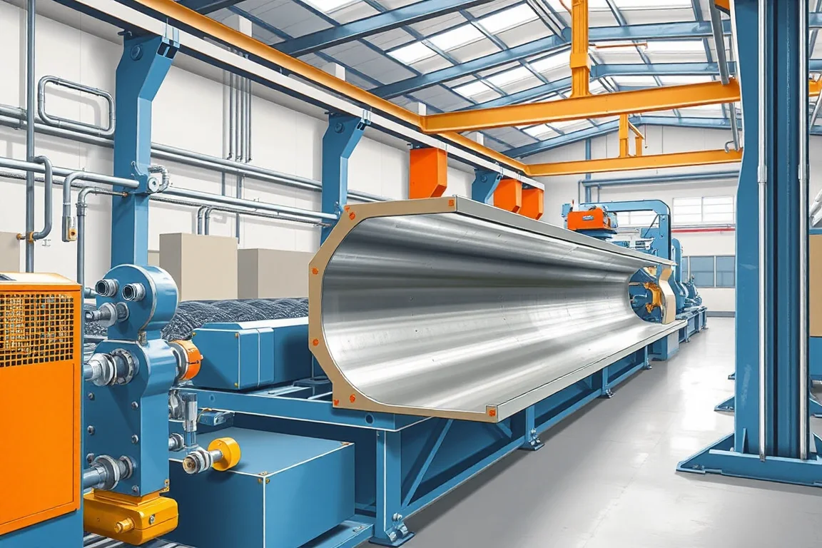
A solar hat channel roll forming machine produces a raised-crown member with outward feet for the specified photovoltaic support arrangement. The crown, sidewalls and mounting feet establish the component's interfaces. The exact section and hole pattern must follow the chosen mounting-system design.
This route differs from a C or U channel and from an aluminum module frame. The hat shape may provide distinct contact surfaces, but its appearance does not establish capacity or universal module compatibility. The machine should be evaluated against the actual part and its mating hardware.
Which hat dimensions define the component?
Show crown width, overall depth, sidewall angles, foot widths and any returns or stiffening features. Identify whether the section is symmetric and which surfaces must meet the supporting structure or attached member.
Use separate values for projected width and developed strip width. The raised sides and returns consume material that is not reflected in the footprint alone. Confirm coil requirements for each approved section.
How should the mounting interfaces be documented?
Provide brackets, clamps or other connection drawings showing how they meet the crown and feet. Identify contact surfaces, fastener access and installed orientation. These details determine which dimensions need functional fit checks.
Do not assume a ceiling hat channel or structural omega section can substitute because the outline is similar. The solar component has its own material, features and system requirements.
What holes or slots are required?
- Feature location on crown, sidewall or foot.
- Size, shape and slot direction.
- Positions from member ends and section datums.
- Required solid zones around connections.
- Part identity and installation orientation.
Where several project patterns share one section, use controlled program identifiers. Similar members with different slots should remain distinguishable through forming, coating and packaging.
How does the forming route develop the section?
Guided strip passes through progressive stages that create the crown, sidewalls and outward feet. The sequence must preserve tool access and the intended relationship between mounting surfaces. Required features are made at the agreed stages.
Cutting separates member lengths, followed by supported discharge. Review how the crown and feet are supported at the cutoff. Local distortion can change a mounting interface even when the middle of the member is correctly formed.
What material and protection route should be specified?
State grade, base-metal thickness and the required surface or corrosion-protection process. Precoated strip and post-fabrication coating need different handoff and final-inspection arrangements. Use the actual specified material for trials.
Inspect bends, slots and contact areas. Retain material identity with approved samples and final records. The machinery brief should reproduce the selected product requirements rather than promise a generic outdoor service life.
How should contact geometry be measured?
Measure crown position, depth, foot spacing and angles on agreed supports. Check whether the intended contact surfaces have the correct relationship without forcing the section flat. Assess straightness and twist separately.
Fit the intended connection hardware after dimensional checks. This connects the measured section to its actual use and can reveal a clearance or access issue that overall dimensions do not show.
Can crown and foot dimensions vary on one line?
Only within the proposed tool design. A crown-width change can move the sidewalls and feet, while a foot-width change may affect holes and strip development. Ask for a full combination matrix rather than independent dimension ranges.
Demonstrate a relevant change through an accepted, fully featured member and hardware-fit check. Include guides, punches, cutting support and inspection in the timing. This shows the real flexibility of the line.
How should feature-rich orders be scheduled?
Compare accepted members from a real sequence of lengths and mounting patterns. A long hat section with few holes can run differently from short pieces with repeated crown and foot features. Record punch changes, cut frequency and order sorting so the output comparison reflects the parts the business actually needs rather than a convenient unfeatured demonstration.
What should the trial and package check include?
- Verify component drawing, material and feature program.
- Measure crown, sidewalls, feet and holes.
- Inspect cut ends and contact surfaces.
- Fit the specified mounting hardware.
- Check straightness and twist.
- Inspect after normal coating and packaging within scope.
- Record accepted output and changeover work.
Bundle restraints should preserve the feet and crown rather than force the members into a convenient stack. Clear product identity is also important where several hat variants look alike.
Frequently asked questions
Is solar hat channel the same as omega purlin?
The names can describe similar outlines, but the complete section, material and connections may differ. Use the controlled component drawing instead of assuming interchangeability.
Does the shape guarantee stronger mounting?
No. Structural suitability depends on the complete mounting-system design, materials and connections. The machine trial verifies the specified component geometry.
Can holes be placed in any part of the profile?
Only the approved design should establish feature locations. Tool access and forming sequence must then be reviewed to manufacture those locations correctly.
Why inspect after bundling?
Local restraint can bend feet or alter their spacing. The delivered member must retain the geometry and hardware fit approved during production.
What information makes quotations comparable?
Provide the full section, material and coating route, features, hardware references, lengths and variant matrix. State the same handling and acceptance requirements for every proposal.
Make the crown and feet one controlled interface
A solar hat-channel line should be specified through its actual mounting relationships. Combining geometry, features and delivered condition gives the equipment trial a clear target without inventing system-performance claims.

Continue your research
- Solar Mounting Roll Forming Machines
- Solar Strut Channel Roll Forming Machine
- Solar Mounting Rail Roll Forming Machine
- Solar C Channel Roll Forming Machine
- Solar U Channel Roll Forming Machine
- Solar Purlin Roll Forming Machine
- How Solar roll forming machine Works
- How To Choose a Solar roll forming machine
- Solar roll forming machine Price: What Affects the Cost?
Configuration & specification inputs
Match the configuration to your section drawing, material and production requirements.
| Parameter | Requirement / confirmation needed |
|---|---|
| Profile geometry | Approved solar hat crown, sidewalls, outward feet, returns and contact relationships. |
| Material | Specified mounting-system steel grade and final surface-protection route. |
| Thickness & grade | Grade-thickness combinations paired with crown, depth and foot geometry. |
| Process route | Registered crown or foot features, progressive hat forming, supported cutting and identified handling. |
| Cutting | Project lengths with preserved mounting faces and end-feature relationships. |
| Output | Accepted hat members including actual feature density, cut frequency and order sorting. |
| Electrical supply | Utilities for punching, forming, cutoff and the defined finishing handoff. |
| Acceptance | Crown and feet, holes, unforced contact geometry, hardware fit and condition after packaging. |