
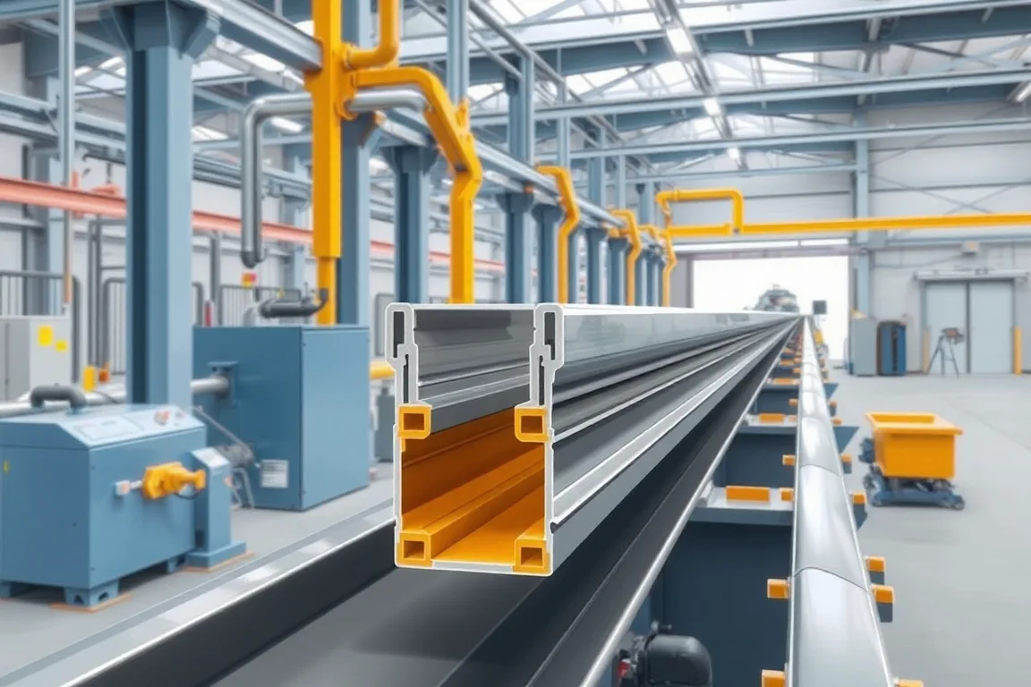
A Z channel production line is a roll forming system configured for a profile whose two flanges sit on opposite sides of the web, producing a step or offset rather than a symmetrical section. That offset makes the part orientation-sensitive: in service the channel carries load or locates panels in one specific direction, and the installed geometry depends on which way each flange faces. The section is usually a constant cross-section, which favors roll forming, but the functional requirements become tighter because the two flanges act as separate datums and can be punched, lipped, or cut asymmetrically.
This page treats the Z channel as an application: what the drawing must show, how the production line handles the offset, where roll forming stops and assembly or finishing begins, and how to inspect a profile that does not look the same from both ends. It does not quote a machine size or imply that any Z shape can be formed without a feasibility review.
What defines a Z channel and why the offset matters
A Z channel has a web and two flanges bent in opposite directions, so one flange sits on each side of the web plane. Unlike a C channel, where both flanges face the same way and the section is broadly self-symmetric, the Z profile has no mirror symmetry across the web. The two flange toes may be plain, lipped, or have returns, and the bend angles are not necessarily equal. Where a Z channel joins another member, one flange typically overlaps or seats against a mating surface while the other stays free or provides stiffness.
Because of that asymmetry, the drawing must show more than the overall width and height. It should identify the functional datums: the web face, a specific flange outside face, hole centerlines referenced to one flange, and the direction of any lip or hem. Without a datum callout, a fabricator or a forming line setup can produce a section that measures correctly but installs mirrored, with holes on the wrong side of the web or the lip facing the wrong direction.
Drawing inputs that drive the production line
A complete cross-section is the starting point, but the line is configured around the features that must repeat accurately. These include the bend radii and bend development, the flange lengths and their tolerances, any holes or cutouts and whether they are formed in-line or off-line, and the mating interfaces where the channel meets other parts. Hole position should be dimensioned from the functional datum, not from an arbitrary edge, because forming and cutting variation can shift an edge while the datum stays correct.
Handedness deserves explicit treatment. Some Z applications use a left-hand and a right-hand version that differ only by the direction of the offset or the position of holes. If the drawing does not label the hand or show the orientation in the installed assembly, there is a real risk of producing a batch that is dimensionally sound but unusable on one side of the structure. The line may need either two tooling sets, a reversible feature, or a clear marking and segregation procedure. That decision affects tooling cost and changeover time, so it belongs in the early drawing review.
Material and thickness as feasibility inputs
Z channels are produced from specified steel, stainless steel, or nonferrous strip after a feasibility review. The material grade and base-metal thickness are buyer inputs, and the operating range of the line requires supplier verification against the actual strip. Material choice influences bend development, springback, and surface finish. Stainless steel and some high-strength steels spring back differently from mild steel, so a bend angle that forms correctly in one grade may need different tooling or overbend in another. Coating and surface finish also matter if the flange is visible or if the forming rolls could mark the surface.
Thickness interacts with the offset geometry. A heavier web and flange set requires more forming force and may limit how tight a bend radius can be achieved before cracking or excessive thinning at the bend. Incoming strip variation, including thickness tolerance and edge condition, should be stated because a line set for one coil lot may need adjustment for another. None of this is a universal rule; it is a set of inputs the feasibility review uses to confirm whether the profile can be formed progressively and cut cleanly.
Production route: feasibility review to cutoff
A typical route for a Z channel line is feasibility review, coil preparation, progressive forming, secondary features, and cutoff. Each stage has a distinct purpose. The feasibility review checks whether the offset bends can be developed in sequence, whether tool access exists for any lip or return, and whether the holes can be placed without interfering with forming stations. Coil preparation covers loading, straightening if needed, and feeding the strip consistently. Progressive forming builds the section through a series of stations, gradually turning the flanges and any lips while maintaining the web as a reference. Secondary features such as punches, notches, or embosses may be added before or after forming depending on access and part handling. Cutoff separates the finished length.
The sequence matters because forming a flange before punching can distort the section, while punching flat strip before forming can place holes accurately but may stretch or move them as the bends develop. The feasibility review should identify which features are formed in-line and which are added later. If a feature cannot be produced in-line without damaging the profile, it may need a separate operation, which changes the assembly boundary and the quotation scope.
How forming stations handle the offset geometry
In progressive forming, each station makes a partial bend, and the strip moves through a sequence that gradually brings the flanges to their final angles. For a Z profile, the two flanges bend in opposite directions, so the tooling must support the web while forming each side. If the flanges are formed simultaneously, the strip can twist because the forces are not balanced. Staging the bends, or using guide features that keep the web registered, helps maintain the offset. The web is usually the primary datum through the line, and the flange positions are derived from it.
Enclosed or re-entrant features restrict tool access. A tight return or a hem on a flange may require a station where the roll cannot reach into the corner, so the feature is formed in a later station or with a different tool geometry. The feasibility review should describe how each bend develops and where the strip is supported. This is also where springback compensation is considered: the rolls may be set to overbend slightly so the released profile meets the angle after the strip leaves the station. Adjusting moving machinery is a task for the equipment supplier or trained personnel, not something to attempt from a general description.
Secondary features, punching, and notching
Holes, slots, and notches are common in Z channels because the profile often serves as a purlin, a frame member, or a mounting rail. In-line punching can be efficient for repeated patterns, but it requires access to the web or flange before the section is closed. If a hole must be on a flange that is already formed, the punch tool may need to approach from an angle or the part may need to be processed off-line. Notches at the ends affect how the channel mates with other components; a notch that is dimensioned from the wrong datum can leave a gap in the assembly even if the hole positions are correct.
The quotation should distinguish between standard hole patterns and special features. A line configured for a plain Z channel is not the same as one configured with punch dies, notching stations, and custom end tooling. Keeping plain Z channel production separate from extra tooling for punches, lips, or nonstandard end features helps avoid comparing options that are not equivalent. If the part requires several secondary features, the assembly boundary shifts and the line scope should be written to match the finished part, not just the formed section.
Cutoff requirements and end quality
Cutoff is the last in-line operation and it determines the end quality of the part. The cutoff method must be compatible with the profile: a shear that works on a flat strip may crush or distort a Z section, especially if the cut passes through a flange. A profile-supported cutoff uses tooling that holds the section during the cut so the ends stay square and the flanges are not deformed. The cut length and any secondary operations at the ends, such as deburring or a formed lip, should be confirmed with the actual profile. End quality also affects how the channel fits into the next assembly step; a burr or a distorted flange can prevent proper seating.
For orientation-sensitive parts, cutoff can also be a point where handedness is preserved or lost. If the line produces both left-hand and right-hand versions, the cutoff and any end features must be set correctly for each. A clear marking or segregation step after cutoff helps prevent mixing.
Acceptance checks: what to inspect and how
Inspection should prioritize functional datums and mating features rather than tolerancing every dimension equally. The web, the flange that seats against another part, and the hole positions referenced to those datums are the critical items. The section should be inspected in a defined free or restrained state, and the measurement method should be documented. A Z channel measured free may show more twist or flange angle variation than the same section restrained in its installed condition, so the acceptance criteria should state which state applies.
For parts that overlap or fit handed, trial adjoining sections together. Check the free-state twist and both ends, because the cut end and the lead end can differ. If the profile has lips or returns, verify that they clear mating components. Keeping plain Z channel production separate from extra tooling needed for punches, lips, or nonstandard end features means the inspection plan should also separate the formed section from the finished part. A first-off piece and a representative steady-production sample, run with the agreed material and gauges, give a better picture than a single trial piece.
Power and installed equipment scope
The buyer states the voltage, frequency, and phase for the intended location. Installed power depends on the confirmed equipment schedule: the number of forming stations, the drive arrangement, the punch and cutoff capacity, and any auxiliary equipment such as coil handling or unload conveyors. These are not generic values; they follow from the line configuration and the profile. The quotation should list the equipment included and identify any items assumed to be supplied by the buyer, such as foundations, compressed air, or material handling.
Output expectations and production target
There is no verified model rating for output. The practical target should be defined as accepted output per shift with the actual profile and material, not as a maximum speed under ideal conditions. Changeover frequency and batch size influence whether dedicated roll tooling is economical. High steady-state speed is less useful for small, varied batches where setup and changeover dominate. Setup scrap, punching time, and unloading time all reduce the usable output, so the production target should account for them.
Practical checklist before approving a line
- Confirm the drawing shows the functional datums and the handedness, including the direction of the offset and any lip or hole pattern.
- State the material grade, base-metal thickness, and incoming strip variation, and confirm the feasibility review covers them.
- Identify which features are formed in-line, which are punched or notched, and which are added off-line.
- Confirm the cutoff method supports the profile and produces acceptable end quality.
- Define the accepted output per shift with the actual profile and material.
- State the electrical supply and obtain a confirmed equipment schedule for installed power.
- Agree on the inspection state (free or restrained), the measurement method, and the functional datums to check.
- Trial adjoining and handed sections where fit matters.
- Separate the quotation scope for engineering, roll tools, punch dies, cutoff tools, and future size changes.
- Record changeover steps, setup scrap, and secondary operation time as part of the production target.
Alternatives to a dedicated Z channel line
Roll forming is not the only route. Press braking can produce Z channels in small batches where the profile is simple and the quantities do not justify dedicated tooling. Stamping can make short sections with complex features but is usually limited by die cost and part length. Extrusion suits nonferrous profiles with constant cross-section but not steel strip. Welded fabrication can build a Z shape from plate or strip when the quantity is low or the geometry is not suited to progressive forming. Each alternative has different implications for hole placement, end quality, and assembly. Comparing them should include the cost of tooling, the batch size, and whether the functional datums can be held consistently. A roll forming line becomes attractive when the section is constant, the volume is sufficient to amortize tooling, and the features can be produced in-line without compromising the profile.
FAQ
Can a Z channel be formed on the same line as a C channel?
Sometimes, but the two profiles have different symmetry. A C channel has both flanges on the same side, while a Z channel has them on opposite sides. The forming stations must support the strip differently, and the punch and cutoff tooling may need to change. If the line is intended to run both, the changeover procedure and the tooling commonality should be confirmed during the feasibility review rather than assumed.
How do I prevent mirrored holes on a Z channel?
Show the datum and the handedness on the drawing, including the installed orientation and the side of the web where holes belong. Dimension hole positions from the functional datum rather than from an edge. If left-hand and right-hand parts are both required, label them and plan segregation after cutoff. A trial assembly with adjoining parts is the most direct check.
What determines whether holes are punched in-line or off-line?
Access and distortion. If the punch can reach the web or flange before the section is closed, in-line punching is practical. If a hole is on a formed flange or in a tight corner, off-line drilling or punching may be needed. Forming after punching can move hole positions, so the feasibility review should confirm the sequence for the specific profile and material.
Why does the free-state measurement differ from the installed measurement?
A Z channel released from the forming line can twist or spring because the two flanges are not balanced. When it is restrained in the installed assembly, the mating surfaces may pull it into a different shape. Acceptance criteria should state whether the part is measured free or restrained, and the method should be documented so both parties interpret the result the same way.
What should be included in the cutoff specification?
Confirm the cutoff method is profile-supported, the cut length and end squareness, and whether any secondary operation is needed at the ends. For handed parts, confirm the cutoff does not mix orientations. The specification should describe the actual profile, not a flat strip, because a Z section can distort in a shear that is not designed to hold it.
How should future size changes be handled in the quotation?
Separate engineering, roll tools, punch dies, cutoff tools, and future size changes. A line that is cheaper initially may make later product changes expensive if the tooling cannot be adapted. Ask how a change in flange length, offset, or hole pattern would be accommodated, and whether new tools or only adjustments are required. This is a commercial and engineering decision, not a universal rule.

Continue your research
- Custom & Industrial Profile Roll Forming Machines
- Custom Profile Roll Forming Machine
- Hat Channel Roll Forming Machine
- C Channel Production Line
- Electrical Cabinet Frame Roll Forming Machine
- Elevator Profile Roll Forming Machine
- How Custom profile roll forming machine Works
- How To Choose a Custom profile roll forming machine
- Custom profile roll forming machine Price: What Affects the Cost?
Configuration & specification inputs
Match the configuration to your section drawing, material and production requirements.
| Parameter | Requirement / confirmation needed |
|---|---|
| Profile geometry | A custom Z channel has offset flanges and an orientation-sensitive installation. Show the datum and handedness on the drawing to avoid mirrored holes or cut features. |
| Material | Specified steel, stainless steel or nonferrous strip after feasibility review |
| Thickness & grade | Buyer to specify base-metal thickness and grade; operating range requires supplier verification. |
| Process route | Feasibility review → coil preparation → progressive forming → secondary features → cutoff |
| Cutting | Confirm profile-supported cutoff, cut lengths, end quality and any secondary operations. |
| Output | Define accepted output per shift with the actual profile and material. |
| Electrical supply | Buyer to state voltage / frequency / phase. Installed power requires a confirmed equipment schedule. |
| Acceptance | Trial adjoining sections where overlap or handed fit matters. Check free-state twist and both ends. Keep plain Z-channel production separate from extra tooling needed for punches, lips or nonstandard end features. |