
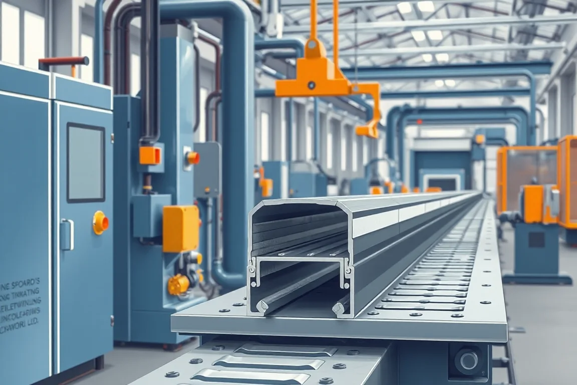
A C channel production line transforms coiled metal strip into a continuous lipped section whose geometry serves structural, mounting, or enclosure functions. Unlike a simple U channel, the C profile carries return lips that stiffen the flanges and create mating interfaces for fasteners, clips, or adjacent components. This page addresses the line itself: how its modules interact, which production route suits which order pattern, and how to inspect parts against functional requirements rather than nominal shape alone.
What defines a C channel beyond two bends
A C channel begins as a strip that is progressively bent into a web, two flanges, and inward-turning lips. The lips close the section partially, increasing stiffness and providing edges that can grip, locate, or protect. In many assemblies, the critical features are the inside web width, the lip gap, the flange height, and the position of holes or slots relative to those datums. A line that produces the outer silhouette but drifts on lip clearance or hole location can fail assembly even when the section looks correct on a profile projector.
The functional drawing should distinguish between surfaces that mate, surfaces that fasten, and surfaces that only shield. That distinction drives where tolerances concentrate and which stations need adjustment during setup. A line built for a decorative channel may share forming principles with an industrial C channel but will differ in stand count, tool access, and cutoff support.
Component interfaces along the line
A C channel production line is a sequence of modules whose interfaces determine achievable quality. The coil handling interface accepts strip width, thickness, and coil mass; inconsistency here propagates through every downstream station. The forming interface is a series of stands, each contributing a controlled bend increment. The secondary-feature interface, typically punching or notching, acts on the moving or indexed strip before final shape is locked. The cutoff interface separates the finished section while preserving end geometry and length.
Each interface has a boundary condition. Coil preparation may include a straightener or feeder whose grip must suit the strip surface. Progressive forming must develop bends without exceeding the material's forming limits, which depend on grade, temper, and thickness. Punching must occur where the strip is flat or accessible enough for the die. Cutoff must support the profile so the cut does not collapse lips or twist the section.
Profile route versus alternative fabrication routes
Roll forming is one route among several. Press braking can produce C sections in small quantities with simple tooling, but each bend is a separate handling step and length consistency depends on operator skill. Stamping can create complex features in a single stroke but ties the part to a dedicated die and usually limits length. Extrusion suits nonferrous sections with constant cross-section but not typical steel C channels. Welded fabrication builds a channel from plates or strips, offering size flexibility at the cost of distortion control and labor.
Roll forming becomes attractive when the cross-section is constant along the length, bend development is feasible, and order volume justifies dedicated tooling. It becomes less attractive when the profile changes along the length, when quantities are very small and varied, or when the material is difficult to form without cracking. The production route should be chosen on the drawing and order pattern together, not on the shape name alone.
Feasibility review before committing to tooling
Feasibility review examines whether the proposed C channel can be formed from the specified strip without defects such as edge cracking, flange buckling, or lip distortion. It considers bend radii relative to thickness, the sequence of bends, and whether re-entrant lips restrict tool access. A profile with tight lips and deep flanges may require split tooling or a different bend order than a simple U channel.
The review also checks hole and slot placement against forming stations. Holes placed too close to a bend may distort. Slots that cross a bend line may need to be punched after forming or not at all. The outcome of feasibility review is not a guarantee but a documented basis for tool design and a decision about whether to proceed.
Coil preparation and strip condition
Coil preparation covers uncoiling, straightening, and feeding. The strip's incoming condition matters: camber, crossbow, thickness variation, and surface finish all affect how the material enters the first forming stand. A strip with residual curvature can cause the section to twist or the flanges to run out of square. Straightening reduces these effects but adds an interface that must be set for the actual material.
Coil changes also interrupt production. The line's coil handling interface should allow splices or rethreading without losing the strip's alignment through the forming stands. The time and scrap associated with coil changes belong in the production plan, not treated as an afterthought.
Progressive forming and bend development
Progressive forming distributes the total bend angle across multiple stands. Each stand performs a fraction of the bend, which limits strain and helps control springback. The number of stands and the angle per stand depend on the profile complexity and material. A C channel with return lips may require additional stands to form the lips after the flanges, or a sequence that forms lips and flanges together in a controlled way.
Tool access is a practical constraint. Enclosed or re-entrant features can make it difficult to place forming rolls or to remove the section after forming. The line designer must consider how the strip enters and exits each stand and whether the profile can be supported throughout. This is where a C channel differs from a Z channel or a simple angle: the return lips create a partially closed geometry that affects roll placement and stripping.
Secondary features: punching, notching, and slots
Secondary features are holes, slots, notches, or embosses that the C channel needs for fastening or assembly. In a roll forming line, these are typically created by punching or notching stations integrated between forming stands or after forming. The station must match the strip's position and speed, and the die must be robust enough for the material and thickness.
Punching before forming is easier for flat geometry but can distort holes during bending. Punching after forming requires access to the formed section and may need a mandrel or support to prevent collapse. The choice affects tooling cost, setup time, and hole location accuracy. The drawing should specify which features are critical and what deviation is acceptable.
Cutoff and end quality
Cutoff separates the finished section to length. The cutoff tool must support the profile so the cut does not deform lips, twist the section, or leave a burr that interferes with assembly. For a C channel, cutoff may use a shear, a saw, or a punch-type cutter, each leaving a different end condition. The method should be chosen based on the material, thickness, and required end finish.
Cut length accuracy and squareness matter when the C channel fits into a frame or abuts another part. The cutoff station's interface with the forming line—whether it runs continuously or indexes—affects cycle time and length consistency. Secondary operations such as deburring or end forming may be needed after cutoff; those should be included in the line scope if they are part of the finished part.
Assembly boundaries: what the line does not do
The production line produces a C channel component; it does not assemble it into a finished product. Assembly boundaries define where the line's responsibility ends. If the C channel is later welded, bolted, or clipped to other parts, those operations occur outside the line unless explicitly included. The line may also perform in-line operations such as marking or light assembly, but these must be specified and tooled.
Confusing production with assembly leads to gaps in scope. For example, a line that punches holes but does not insert fasteners leaves the assembly step to another process. The quotation should separate engineering, roll tools, punch dies, cutoff tools, and any future size changes, so the buyer can see what is included and what is not. The cheapest initial arrangement may make later product changes expensive if it lacks modularity.
Application-specific inspection and acceptance
Inspection should prioritize functional datums and mating features rather than tolerancing every dimension equally. For a C channel, that may mean measuring the inside web width, lip gap, flange height, and hole position relative to the web. The measurement method matters: a section measured in a free state may relax differently than one measured in a restrained state. The drawing or acceptance agreement should define the state and the method.
First-off pieces and a representative steady-production sample should be inspected with the agreed gauges. The material and profile should match the intended production, not an easier demonstration substitute. Records should include changeover steps, setup scrap, punching time, and unloading time. Comparing the written equipment scope with all secondary operations needed for a finished part helps avoid missing steps.
Changeover and batch-size considerations
Changeover frequency and batch size influence whether dedicated roll tooling is economical. A line that runs one C channel continuously can be optimized for that profile. A line that switches between sizes or variants needs rapid changeover features, such as tooling carts, preset adjustments, or numerical control positioning. High steady-state speed is less useful for tiny varied batches because setup time dominates.
The recovery of production quality after changeover is the real measure. The line should return to a previous setting and produce acceptable parts without lengthy trial and error. This depends on how adjustments are made and whether settings are recorded and repeatable. When comparing changeover approaches, use the recovered production quality, not just stand movement time.
Checklist for specifying a C channel production line
- Provide the complete cross-section, including functional datums, bends, holes, and mating interfaces.
- State the material grade, thickness, and surface condition, and note any incoming strip variation that may occur between batches.
- Define which dimensions and features are critical for assembly and which can tolerate wider variation.
- Describe the intended production route: coil preparation, progressive forming, secondary features, and cutoff.
- Specify cutoff requirements: profile support, cut length, end quality, and any secondary operations.
- State the electrical supply voltage, frequency, and phase; installed power requires a confirmed equipment schedule.
- Define accepted output per shift with the actual profile and material, not a theoretical maximum.
- Include changeover frequency and batch size to evaluate tooling economics.
- Separate engineering, roll tools, punch dies, cutoff tools, and future size changes in the quotation scope.
- Agree on inspection method and state (free or restrained) for functional datums and mating features.
Comparing production alternatives
Press braking offers flexibility for low volumes and simple C sections, but each bend is a separate operation and length consistency depends on operator skill. Stamping can produce complex features quickly but requires a dedicated die and usually limits part length. Extrusion works for nonferrous constant cross-sections but not typical steel C channels. Welded fabrication allows large or custom sizes but introduces distortion and labor. Roll forming suits constant cross-sections at volume, with dedicated tooling and integrated secondary operations. The choice should follow the drawing, material, and order pattern.
FAQ
What is the difference between a C channel and a U channel in production?
A C channel has return lips that turn inward from the flange edges, creating a partially closed section. A U channel has no lips. The lips add stiffness and provide edges for fastening or locating. In production, lips require additional forming stands and can restrict tool access, so a C channel line is generally more complex than a U channel line.
Can a C channel production line make different sizes?
Yes, if the line is designed for changeover. Different sizes may require different roll tooling or adjustable stands. The practicality depends on batch size and changeover frequency. A line dedicated to one size can be simpler and faster, while a line for multiple sizes needs features that allow repeatable setup changes.
How are holes added to a C channel during roll forming?
Holes are typically added by punching or notching stations integrated into the line. They can be punched before forming, after forming, or between forming stands. The choice depends on hole location, material, and whether the hole would distort during bending. The die must be designed for the strip position and speed.
What inspection is needed for a C channel production line?
Inspection should focus on functional datums and mating features. This may include inside web width, lip gap, flange height, and hole location. The section should be measured in a defined free or restrained state, and the method should be documented. First-off and steady-production samples should be checked with agreed gauges.
How does material thickness affect the production line?
Thickness affects forming forces, bend radii, springback, and tool clearance. A line set for one thickness may not produce acceptable parts at a different thickness without adjustment or different tooling. The operating range requires supplier verification, and the buyer should specify base-metal thickness and grade.
What should be included in a quotation for a C channel production line?
The quotation should separate engineering, roll tools, punch dies, cutoff tools, and future size changes. It should also clarify which secondary operations are included and which are not. The scope should cover coil preparation, forming, secondary features, and cutoff, along with changeover and batch-size assumptions.

Continue your research
- Custom & Industrial Profile Roll Forming Machines
- Custom Profile Roll Forming Machine
- Hat Channel Roll Forming Machine
- Z Channel Production Line
- Electrical Cabinet Frame Roll Forming Machine
- Elevator Profile Roll Forming Machine
- How Custom profile roll forming machine Works
- How To Choose a Custom profile roll forming machine
- Custom profile roll forming machine Price: What Affects the Cost?
Configuration & specification inputs
Match the configuration to your section drawing, material and production requirements.
| Parameter | Requirement / confirmation needed |
|---|---|
| Profile geometry | A custom C channel differs from a U channel through its return lips and intended interfaces. Specify the functional inside dimensions and lip clearances for the mating assembly. |
| Material | Specified steel, stainless steel or nonferrous strip after feasibility review |
| Thickness & grade | Buyer to specify base-metal thickness and grade; operating range requires supplier verification. |
| Process route | Feasibility review → coil preparation → progressive forming → secondary features → cutoff |
| Cutting | Confirm profile-supported cutoff, cut lengths, end quality and any secondary operations. |
| Output | Define accepted output per shift with the actual profile and material. |
| Electrical supply | Buyer to state voltage / frequency / phase. Installed power requires a confirmed equipment schedule. |
| Acceptance | Run the required sizes and return to a previous setting. Measure functional interfaces and hole locations after cutoff. Use the recovered production quality, not just stand movement time, when comparing changeover approaches. |