
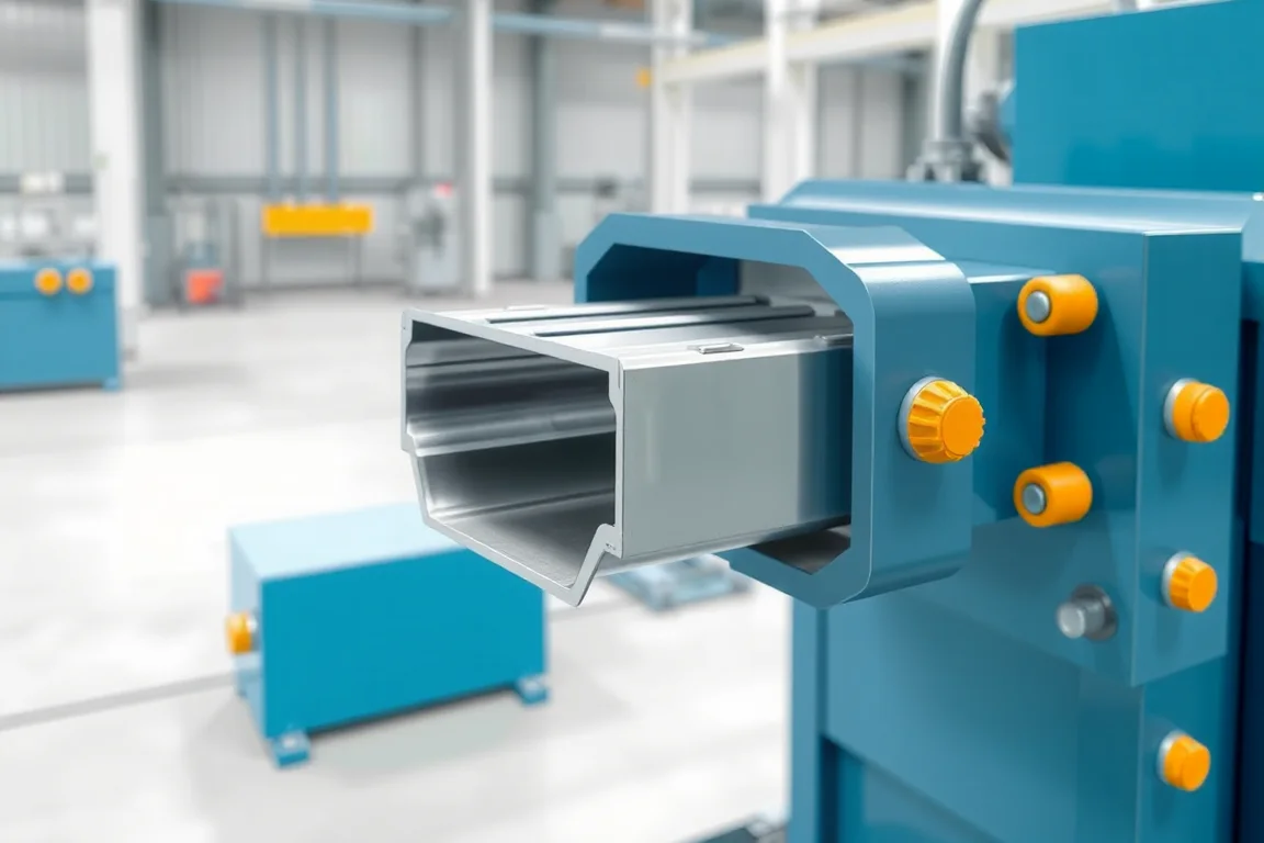
A cable support channel roll forming machine produces the specified channel or strut used to mount cable-support brackets and related components. Its functional edges, slots and connection surfaces matter more than the general C or U outline. The product should be defined with the fittings it is intended to retain.
This route is different from manufacturing a wide cable tray. A support channel is a mounting member; the tray, brackets and other hardware form the wider system. The machine must reproduce the channel's actual interface rather than assume any slotted section will accept the intended fittings.
Which channel family is required?
Provide the full cross-section, including opening width, depth, web, flanges and any inward returns. Identify whether the product uses channel nuts or another specific fitting. Small dimensions at the return can determine engagement.
Record the material and finish with the profile. Two channels with the same outside size can have different openings, returns or thicknesses and may not accept the same hardware.
How should fittings guide the specification?
Use the intended nut, bracket or connector drawings and samples. Show which surfaces make contact and how the fitting is inserted or retained. The inspection plan should check those relationships without improvising substitute hardware.
Do not infer load capacity from a successful fit. Manufacturing acceptance establishes geometry and component compatibility; the support system's design and testing determine its application limits.
What should the slot pattern contain?
- Slot or hole dimensions and orientation.
- Pitch and relationship to cut ends.
- Transverse position on the channel web.
- Required solid margins or unpunched variants.
- Permitted edge condition after punching and cutting.
Trial several lengths so end margins and feature registration are demonstrated. A repeating pattern that works on one stock length may leave an unwanted partial feature when the length changes.
How is the functional return formed?
Progressive tools develop the web, flanges and inward edges while maintaining the opening needed by the fitting. The sequence and actual material determine the final return geometry. A visually similar curl is not enough if its contact surface differs.
Ask how feature making is sequenced with forming. The slot pattern and its condition should be inspected in the finished channel, including areas affected by bending and tool contact.
How should materials and coating routes be compared?
State grade or alloy, base-metal thickness and the specified corrosion-protection process. Precoated steel, post-fabrication coating and stainless variants should be reviewed as distinct production combinations where relevant.
Check the fitting interface in the required delivered condition. Coating and final processing can affect close clearances, so responsibilities for final inspection need to be clear. Retain material and batch identity through the route.
Can shallow, deep and back-to-back channels share equipment?
Different depths or returns may require tools beyond a width adjustment. A back-to-back assembly adds a joining operation to individual channel production. Define each saleable product and identify which process completes it.
Ask for a variant matrix covering rolls, punches, cutoff and any joining fixtures. Demonstrate the first accepted product after changeover with the intended fitting, not only an outside-dimension measurement.
What should cutoff and handling preserve?
The cut ends should leave usable returns and an acceptable edge condition. Inspect local opening changes and burrs separately from the central section. Short pieces may need different transfer support from long stock lengths.
Review stacking so returns are not crushed or spread. A channel that accepts its fitting at the machine exit should remain functional after normal bundling and delivery preparation.
How should different fitting families be kept separate?
Assign a controlled product reference to each return geometry and its compatible hardware. A shared outside size should not allow two channel families to use the same unidentified setup sample. Keep inspection gauges, programs and bundle labels tied to the correct fitting reference so repeat orders reproduce the intended interface rather than merely a familiar channel outline.
What does complete acceptance look like?
- Confirm section, material and fitting references.
- Measure opening, returns, depth and web geometry.
- Check slot pattern and end registration.
- Fit the intended nuts, brackets or connectors.
- Inspect end quality and straightness.
- Recheck interface condition after normal packaging.
- Record accepted output for the stated length and variant mix.
Include any required joining or downstream finishing in the scope or identify it separately. This prevents a basic channel former from being mistaken for a complete support-hardware manufacturing system.
Frequently asked questions
Is support channel the same as cable tray?
No. The channel is typically a mounting member, while the tray provides the defined cable route. Their sections and accessory interfaces need separate specifications.
Will any channel nut fit?
Do not assume that from outside dimensions. Opening, return geometry, thickness and final finish affect the intended interface. Use the specified hardware in trials.
Are slotted and plain channels one product?
They may share a section but have different feature scope and production cycles. Maintain clear variants and verify the pattern or absence of features for each order.
Does the machine make back-to-back assemblies?
Only if the required joining process is included. Producing two individual channels is not the same as delivering a completed joined support member.
What should be supplied for quotation?
Provide the section, fitting samples, material and coating route, slot pattern, lengths and variants. Identify any joined products and their downstream operations.
Specify the fitting interface first
A cable-support channel line should reproduce the returns and opening that make its hardware usable. Linking those features to slot registration and final finish produces a clear, practical equipment acceptance target.

Continue your research
- Cable Tray Roll Forming Machines
- Cable Tray Roll Forming Machine
- Cable Ladder Roll Forming Machine
- Solid Bottom Cable Tray Roll Forming Machine
- U Channel Cable Tray Roll Forming Machine
- Width Adjustable Cable Tray Roll Forming Machine
- How Cable tray roll forming machine Works
- How To Choose a Cable tray roll forming machine
- Cable tray roll forming machine Price: What Affects the Cost?
Configuration & specification inputs
Match the configuration to your section drawing, material and production requirements.
| Parameter | Requirement / confirmation needed |
|---|---|
| Profile geometry | Controlled support-channel opening, web, flanges and functional returns matched to specified fittings. |
| Material | Approved steel or other reviewed material with the required delivered corrosion-protection route. |
| Thickness & grade | Material-thickness combinations verified with channel returns and intended hardware. |
| Process route | Registered slotting, channel and return forming, cutting and separately defined joining or finishing. |
| Cutting | Lengths with usable returns and controlled slot-to-end registration. |
| Output | Accepted fitting-compatible channels including variant changes and package-condition checks. |
| Electrical supply | Utilities for feature tools, forming, cutoff and any explicitly included joining operations. |
| Acceptance | Opening and return geometry, slots, intended nuts or brackets, ends and final-condition fit. |