
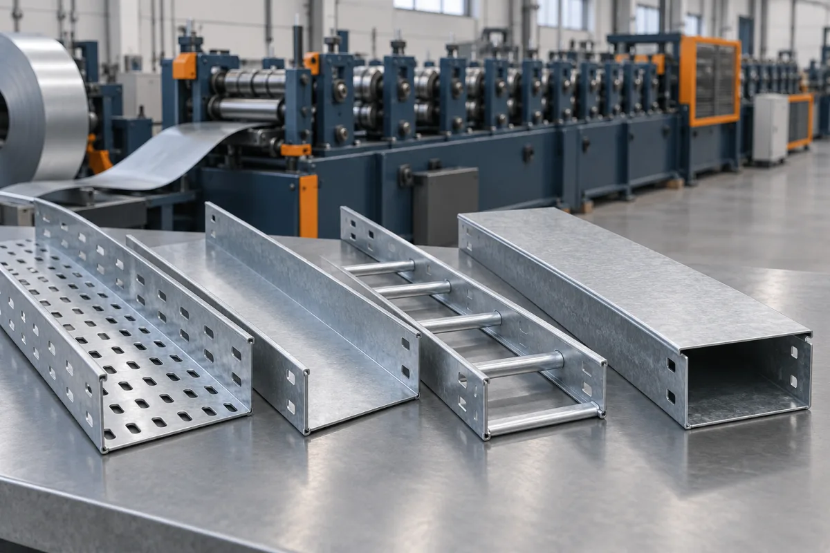
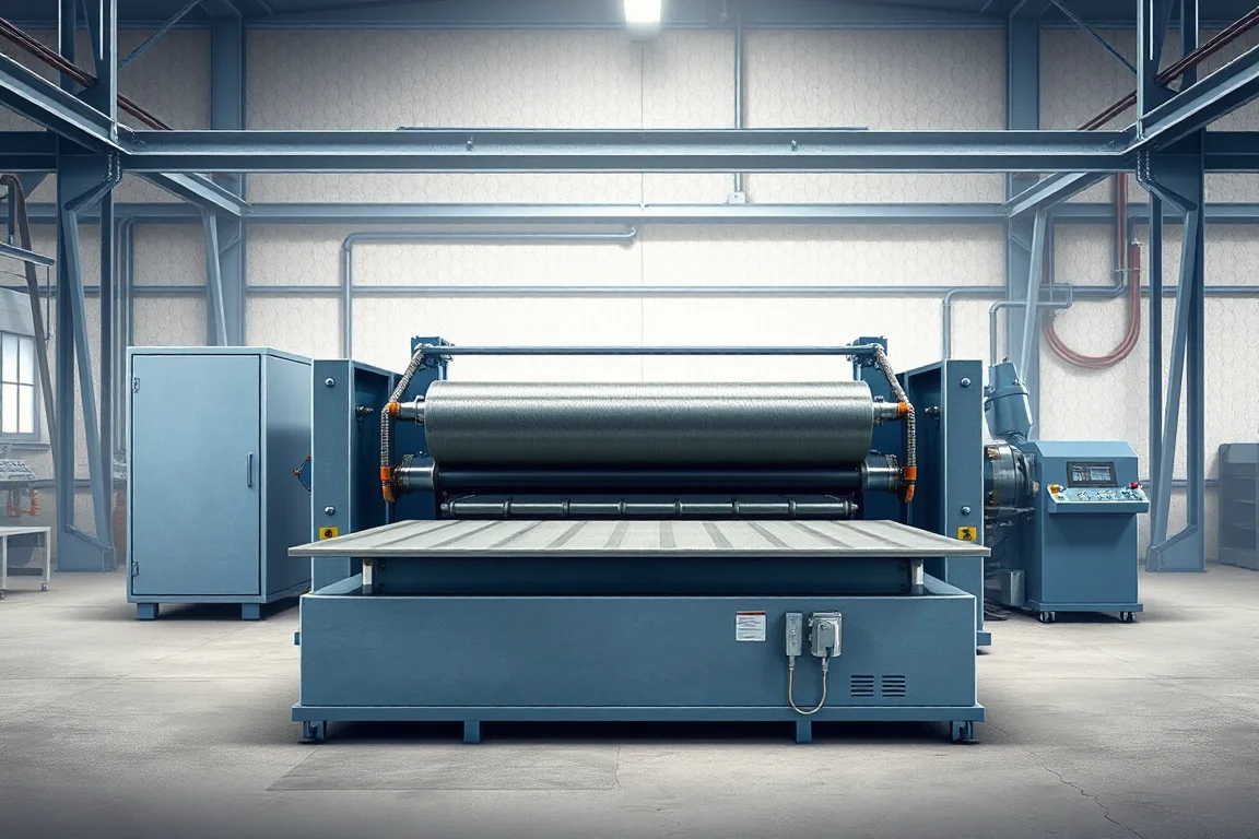
Cable-management production includes formed-bottom trays, ladder components, enclosed trunking and perforated variants. They support related electrical installations but do not share one universal manufacturing route. Define the finished component, its cover or coupling interfaces and its feature pattern before selecting roll-forming and punching equipment.
Choose the correct product construction
A formed tray has a base and sidewalls, with lips or returns where specified. A cable ladder combines rails and rungs through its defined assembly route. Trunking includes its own enclosure and cover requirements. Perforation adds a feature-making task that must be coordinated with bends and cut lengths.
- Cable Tray: compare widths, sidewalls, returns and coupling details.
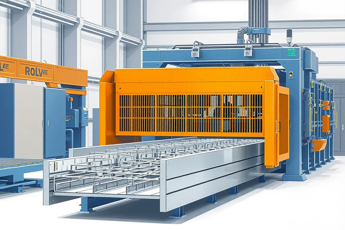
- Cable Ladder: identify rail, rung and assembly operations separately.
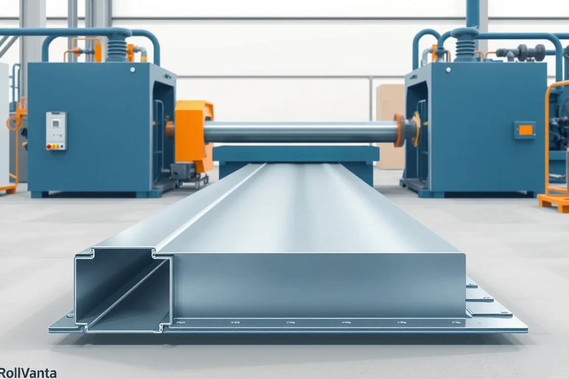
- Cable Trunking: review body, cover and joint interfaces.
- Perforated Tray: specify the hole pattern, bend clearances and scrap-handling route.
Define the complete size and feature matrix
List tray or trunking width, wall height, returns, material and hole patterns as complete products. A width-adjustable line may still need different dies, guides or cutting components. Covers and accessories should have their own drawings and stated production method.
Identify functional inside clearances and the mating coupler or cover. Outside dimensions alone may not establish assembly. Use representative fitting samples during tool approval rather than postponing those checks until installation.
Coordinate perforation with forming
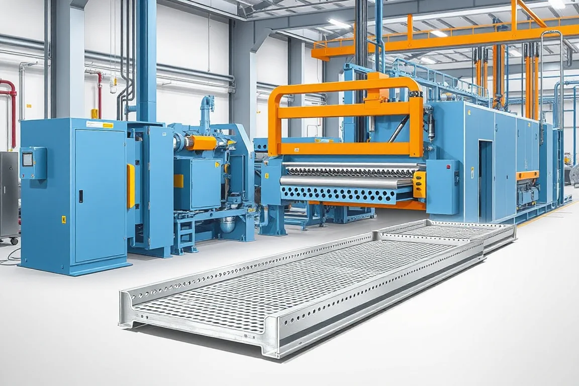
Specify hole shape, repeat, burr requirements and clear areas around bends or functional edges. Define how the pattern relates to cut ends and any coupling holes. A visually similar perforated base can still be wrong for the intended tray if these relationships are omitted.
Ask which operations happen before or after forming and how scrap is handled. For a ladder route, define the production and joining of rungs separately. The complete equipment package should identify every step needed for the supplied component.
Review material and finish requirements
Specify grade, thickness convention, coating and later finishing where applicable. Galvanized and stainless products need their own material and surface requirements. The same nominal thickness does not establish identical forming or edge-quality results.
Use representative production material in trials and inspect tight returns, holes and cut edges. Compare the product before and after discharge to identify damage introduced during handling. Keep material identity with approved samples for later reference.
Test changes and assembled fit
Demonstrate important width and height transitions, including the first accepted component after setup. Confirm how feature positions follow the new size. A rapid movement of forming stands does not establish that the perforation and coupling requirements remain correct.
Trial covers, couplers, brackets or other specified fittings on complete samples. For ladders, inspect the assembled rail-and-rung product. Keep system-level loading or installation requirements tied to the defined design rather than the machine's adjustment range.
Compare usable output and the full package
Measure accepted components with their required features and downstream operations. Dense perforation, size changes, assembly and packing can determine output more than the former's uninterrupted speed. Include inspection, identification and normal handling in the stated trial boundary.
Prepare drawings for bodies, covers and accessories, the material matrix and a representative order schedule. The detailed pages below separate the different routes and help identify missing dies, secondary equipment or assembly work before quotations are compared.
Continue your research
- Cable Tray Roll Forming Machine
- Cable Ladder Roll Forming Machine
- Cable Trunking Roll Forming Machine
- Perforated Cable Tray Production Line
- Solid Bottom Cable Tray Roll Forming Machine
- U Channel Cable Tray Roll Forming Machine
- Cable Support Channel Roll Forming Machine
- Width Adjustable Cable Tray Roll Forming Machine
- GI Cable Tray Roll Forming Machine
- How Cable tray roll forming machine Works
- How To Choose a Cable tray roll forming machine
- Cable tray roll forming machine Price: What Affects the Cost?
- Materials and Thickness for Cable tray roll forming machine
- Production Speed and Output of Cable tray roll forming machine
- Roller, Tooling and Forming Design for Cable tray roll forming machine
- Common Defects and Troubleshooting for Cable tray roll forming machine
- Maintenance Checklist for Cable tray roll forming machine