
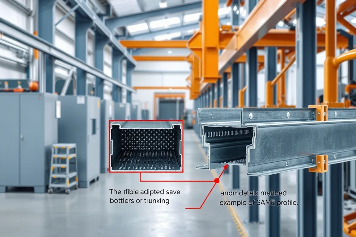
Cable tray roll forming machines turn flat metal coil into long, profiled sections with side walls, returns, and perforations. When output deviates from the drawing, troubleshooting is a structured comparison: does the defect appear before forming, after forming, or after cutting and handling? This guide explains common defect patterns, what evidence to collect, and how to narrow causes while keeping safety boundaries. It is written for production, quality, and maintenance teams who need to diagnose issues without reaching into running machinery or improvising adjustments around stored energy.
Why cable tray roll forming defects rarely have a single cause
A finished cable tray section is the product of several interacting stages: payoff, leveling, punching or perforating, roll forming, cutoff, and handling. Variation in incoming coil, tooling wear, forming sequence, and cut quality can all produce similar symptoms. For example, a warped tray with holes may originate from residual stress introduced during punching, from forming rolls that do not support the perforated web, or from how parts are stacked after cutoff. Treating any one stage in isolation often leads to changes that shift the problem rather than solve it.
The practical approach is to classify the defect by location and timing. Does it appear on every part from a given coil? Does it appear only after a tooling change or a new setup? Is it visible before cutoff when the strip is still supported, or only after the part is handled? Answering these questions narrows the search before any adjustment is considered. The goal is not to guess a fix but to gather evidence that points to a specific stage.
How the process sequence creates and reveals defects
Understanding the sequence helps locate where a defect is introduced. The coil first passes through a payoff, which can influence strip tension and alignment. Leveling then reduces coil set and crossbow; if leveling is insufficient, the strip may enter forming with residual curvature that shows up as twist or camber. Perforation or punching creates holes and may introduce local stress concentrations, especially in the web of a tray. Side forming then bends the edges and returns, and the cutoff separates the finished length.
Each stage has interfaces that matter. The strip must be centered and supported through forming. The perforated area needs adequate roll support to avoid distortion around holes. The cutoff must match the profile and cut cleanly without deforming the section. After cutoff, handling and stacking can introduce dents or twists that were not present on the line. When troubleshooting, compare the part at three points: incoming strip before forming, the formed profile before cutoff where safely observable, and the finished handled part. This comparison separates forming effects from handling effects.
Common defect symptoms and what they suggest
Warped or twisted tray sections. Twist along the length often points to uneven forming, poor strip alignment, or residual stress from punching. If the twist appears only after handling, stacking or cooling may be involved. Compare a flat punched strip with the formed output; if the punched strip is already curved, the perforation stage may be contributing.
Incorrect base width or side height. Dimensional drift can come from roll wear, thermal growth, or material thickness variation. Measure the same location on multiple parts and record the coil lot. A change in material grade or thickness can alter springback and final dimensions.
Burr condition or edge quality. Burrs may originate from the cutoff, from punching, or from roll edges. Inspect the cut end separately from the formed edges. Burrs matter for cable contact and for assembly, so their location helps identify the source.
Cover fit or engagement issues. If covers do not seat properly, the side height, return edge, or hole pattern may be off. Check the cover against a known-good tray from the same setup. A change in one dimension can propagate to cover engagement.
Perforation distortion around holes. Holes may stretch or distort if the web is not supported during forming. This is more likely with wide perforated areas or thinner material. Inspect the area around holes after forming, not just at the punch press.
Diagnostic evidence to collect before adjusting anything
Good troubleshooting starts with documentation, not with turning screws. Record the part identity, coil lot, drawing revision, and measurement conditions. Take measurements at consistent points using the same method. If possible, keep a known-good reference part from a previous run and compare it side by side. Note the time and sequence of any setup change, tooling change, or material change.
Observe the strip at safe points along the line. Do not reach into running machinery. Where guards or interlocks allow observation, note whether the defect is visible before or after a specific stage. If the machine has sensors or readouts, record their values without altering settings. This evidence helps distinguish a material issue from a tooling issue and from a handling issue.
Controlled tests that separate material, tooling, and setup effects
Once evidence is collected, change one controlled variable at a time under the equipment manufacturer’s procedure and with appropriate authorization. For example, if twist is suspected from material, run a short section from a different coil lot with the same setup and compare. If the defect follows the coil, material or leveling is more likely. If the defect follows the tooling, inspect roll condition and alignment. If it follows a setup change, revisit the setup sequence.
Do not adjust moving machinery while it is running. Isolate energy sources before any inspection that requires contact. Any change that affects the qualified process, safety interlocks, or structural performance should be escalated to the responsible engineer. The purpose of a controlled test is to gather evidence, not to achieve a quick fix at the expense of safety or traceability.
How to compare alternatives for troubleshooting and correction
When a defect appears, teams often consider several correction paths. One option is to adjust forming rolls or guides to compensate for the symptom. This can be effective if the root cause is roll wear or misalignment, but it may mask a material issue that will return with the next coil. Another option is to change incoming material or leveling settings. This addresses residual stress but may not help if the tooling is worn. A third option is to modify the cutoff or handling process, which can reduce burrs or dents but will not correct a dimensional drift from forming.
The tradeoff is between speed of correction and durability of the fix. A roll adjustment may restore dimensions quickly, but without understanding why the dimension drifted, the problem may recur. A material change may solve one coil lot but not the next. The most reliable approach is to identify the stage where the defect is introduced, correct that stage, and verify with a known-good reference. This may take longer initially but reduces repeat defects.
Practical checklist for cable tray roll forming troubleshooting
- Record part identity, coil lot, drawing revision, and measurement conditions.
- Compare incoming strip, output before cutoff where safely observable, and finished handled part.
- Check base width, side height, burr condition, and cover engagement.
- Inspect perforated areas around holes after forming.
- Keep a known-good reference part and use the same measurement method.
- Separate forming, cutting, joining, and handling effects.
- Change one controlled variable at a time under the equipment manufacturer’s procedure.
- Escalate safety-related or qualified-process changes to the responsible engineer.
- Do not reach into running machinery or improvise adjustments around stored energy.
FAQ: specific questions about cable tray roll forming troubleshooting
Why does my perforated cable tray twist after forming?
Twist in perforated trays often relates to residual stress introduced during punching and insufficient support of the perforated web during forming. The hole pattern can create localized weak zones that deform unevenly. Compare a flat punched strip with the formed output; if the punched strip is already curved, the perforation stage may be contributing. Also check that the strip is centered and supported through the forming rolls.
What causes dimensional drift in base width or side height?
Dimensional drift can come from roll wear, thermal changes, material thickness variation, or springback differences between coil lots. Measure the same location on multiple parts and record the coil lot. A change in material grade or thickness can alter how the profile forms. If drift follows a tooling change, inspect roll condition and alignment.
How can I tell if a burr comes from cutting or forming?
Inspect the cut end separately from the formed edges. A burr on the cut end points to the cutoff process, while a burr along the formed edge suggests roll condition or strip edge quality. The location of the burr helps identify the source. Burrs matter for cable contact and for assembly, so their presence should be documented and addressed at the correct stage.
Why does the cover not fit properly on the tray?
Cover fit depends on side height, return edge geometry, and hole pattern alignment. If any of these dimensions drift, the cover may not seat. Check the cover against a known-good tray from the same setup. A change in one dimension, such as side height, can propagate to cover engagement. Verify the forming and cutoff stages that affect those dimensions.
What should I do if the defect appears only after handling?
If the defect is not visible before cutoff but appears after handling, the cause may be stacking, cooling, or mechanical damage during transfer. Compare parts immediately after cutoff with parts that have been handled and stacked. Review handling methods and support to prevent deformation. This separation helps distinguish forming issues from post-forming effects.
Can I adjust the machine while it is running to fix a defect?
No. Do not reach into running machinery or improvise adjustments around stored energy. Isolate energy sources before any inspection or adjustment that requires contact. Any change that affects the qualified process, safety interlocks, or structural performance should be escalated to the responsible engineer. Controlled tests should be performed under the equipment manufacturer’s procedure with appropriate authorization.
When to escalate beyond troubleshooting
Some defects indicate issues beyond routine troubleshooting. If the defect affects load rating, electrical continuity, or safety-related features, it should be escalated to the responsible engineer. These characteristics depend on the complete system and its verification, not just on the forming line. Similarly, if a defect persists after controlled tests, or if it involves a qualified process change, further investigation by engineering or the equipment manufacturer may be needed.
Troubleshooting is most effective when it is systematic and documented. By separating stages, collecting evidence, and making controlled changes, teams can resolve common defects and reduce repeat occurrences. The goal is not just to fix the current part but to understand the process well enough to prevent the next defect.
Continue your research
- Cable Tray Roll Forming Machines
- Cable Tray Roll Forming Machine
- Cable Ladder Roll Forming Machine
- Solid Bottom Cable Tray Roll Forming Machine
- U Channel Cable Tray Roll Forming Machine
- Cable Support Channel Roll Forming Machine
- How Cable tray roll forming machine Works
- How To Choose a Cable tray roll forming machine
- Cable tray roll forming machine Price: What Affects the Cost?