
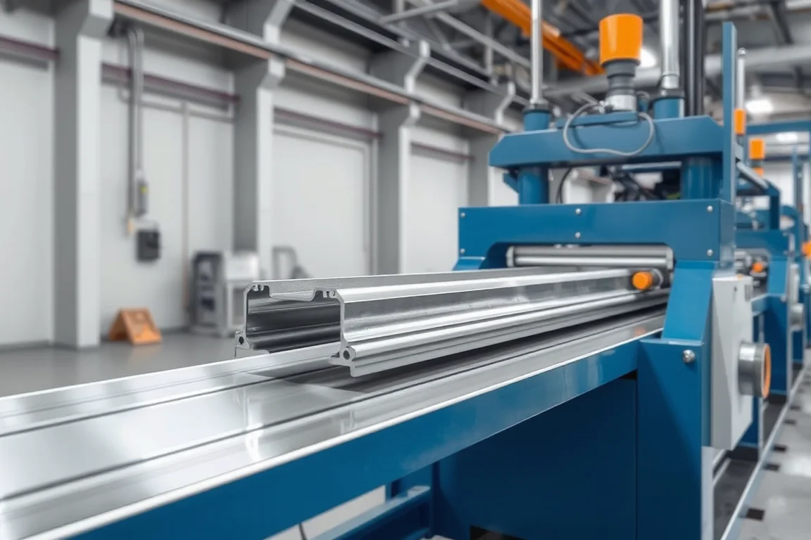
A solid bottom cable tray roll forming machine produces tray sections with a continuous base and raised sides, according to the selected cable-support system. Solid bottom distinguishes the base from a regularly perforated tray; it does not necessarily mean that the sidewalls or connection ends have no holes. Those features must be defined in the product drawing.
The machine specification should connect the tray body to couplers, covers, supports and any end treatment. A broad U-shaped pan is only the starting geometry. The finished tray must preserve usable edges and the interfaces needed to join a complete cable route.
Which parts of the tray are actually solid?
Show the base, sidewalls and end zones separately. Identify any side perforations, drain features or connection holes explicitly. Do not assume a solid-bottom label defines every feature on the product.
If both solid and perforated variants are planned, maintain distinct drawings and programs. Their feature scope and production cycle differ, even where the same side profile and nominal width are used.
What geometry controls the tray and cover?
Define base width, side height, corner radii and the top-edge return or bead. The top detail may retain a cover or provide the specified edge condition. Include cover and coupler drawings where they determine fit.
- Separate internal usable width from outside width.
- Show the complete top-edge shape.
- Define end coupling or overlap details.
- Identify required holes and solid margins.
- State stock lengths and allowable end condition.
A cover should be tested with the actual formed tray. Similar nominal width does not establish matching returns or retention geometry.
How does the continuous base affect forming?
The base spans between the two formed sides and must emerge in the specified condition. Progressive tools develop the sidewalls and top returns while preserving the required tray width and bottom geometry. The material and input width are part of that forming review.
Inspect base shape using agreed supports rather than judging it while the tray is forced flat. Record twist and sidewall angle separately. This helps distinguish overall section deviation from local handling marks.
What feature-making route is needed?
Even a solid-bottom product can require connection holes, side slots or end preparation. Define their positions from the finished tray and cut ends. The proposal should identify whether they are produced before or after forming.
Review accessibility and registration with actual couplers. A line that forms an attractive tray body may still need substantial secondary work if its connection features were omitted from the scope.
How should material and edge quality be specified?
State steel grade or other approved material, base-metal thickness and corrosion-protection route. Precoated strip and coating after fabrication are different arrangements. Identify the correct process and final inspection responsibilities.
Inspect top returns, cut ends and punched features for the agreed edge condition. Cable-contact areas deserve particular attention. The manufacturing brief should define usable product quality without inventing electrical, corrosion or load ratings.
Can one line make different tray widths?
Width adjustment must preserve side height, top-edge geometry and feature positions. Ask which tools move, which input widths are needed and whether cutoff components change. A variable-width former does not automatically make every cover or coupler variant.
Demonstrate a meaningful width change through an accepted tray and matching cover or connection. Include guides, punch settings, cutting support and inspection in the transition.
What does the complete tray range require beyond straight lengths?
Bends, tees, reducers, covers and support hardware can require separate fabrication. List them in the overall product plan so the straight-tray machine is not mistaken for a complete cable-tray factory.
Where a straight length connects to those fittings, use representative references during acceptance. The line should reproduce the intended interface even when the fitting itself is made elsewhere.
How should solid and perforated orders be identified?
Use distinct product references even when both variants share a width and side profile. The label should identify material, finish and connection style as well as base construction. This prevents a visually similar tray from being packed with the wrong cover or supplied under another variant's product documentation.
What should acceptance demonstrate?
- Confirm the solid-base drawing and material.
- Measure base width, side height, returns and twist.
- Inspect connection holes and cut ends.
- Fit intended couplers, covers and support references.
- Demonstrate required width changes.
- Check the product after stacking and packaging.
- Record accepted straight lengths and secondary work.
System loading, electrical continuity and other application requirements need their appropriate product assessment. A dimensional fit trial does not establish those properties by itself.
Frequently asked questions
Does solid bottom mean no holes anywhere?
No. It describes the base construction. Side and connection features still need to be shown on the actual drawing and included in the machine scope.
Can the same line make perforated trays?
Only if the feature-making equipment and approved material route cover the required pattern. A solid-base trial does not automatically validate perforated production.
Are covers included in tray forming?
Not automatically. Covers have their own profile and fabrication route. Provide their interface drawing and identify separate tooling where required.
Can the machine make elbows and tees?
Those fittings often need additional processes. Define their scope separately while checking that the straight tray connects correctly to them.
What should be supplied for quotation?
Send the complete tray section, material, connection features, cover and coupler references, lengths and size matrix. Add the corrosion-protection route and intended bundle format.
Specify the straight tray as part of a connected system
A solid-bottom tray line should deliver more than a wide formed pan. Clear edge, cover and coupling requirements make the equipment proposal practical and give acceptance a useful system-interface target.

Continue your research
- Cable Tray Roll Forming Machines
- Cable Tray Roll Forming Machine
- Cable Ladder Roll Forming Machine
- U Channel Cable Tray Roll Forming Machine
- Cable Support Channel Roll Forming Machine
- Width Adjustable Cable Tray Roll Forming Machine
- How Cable tray roll forming machine Works
- How To Choose a Cable tray roll forming machine
- Cable tray roll forming machine Price: What Affects the Cost?
Configuration & specification inputs
Match the configuration to your section drawing, material and production requirements.
| Parameter | Requirement / confirmation needed |
|---|---|
| Profile geometry | Solid-base tray with defined side height, corner radii, top returns and end-coupling details. |
| Material | Specified tray material and pre- or post-fabrication corrosion-protection route. |
| Thickness & grade | Base-metal thickness combinations paired with tray width, sides and material grade. |
| Process route | Strip preparation, specified side and end features, base-and-side forming, cutting and supported stacking. |
| Cutting | Tray lengths with usable cable-contact edges and registered connection features. |
| Output | Accepted straight tray lengths including cover and coupling checks and required width changes. |
| Electrical supply | Utilities for feature making, forming, cutoff and tray handling equipment. |
| Acceptance | Base shape, width, sides, returns, couplers, covers, edge quality and packaged condition. |