
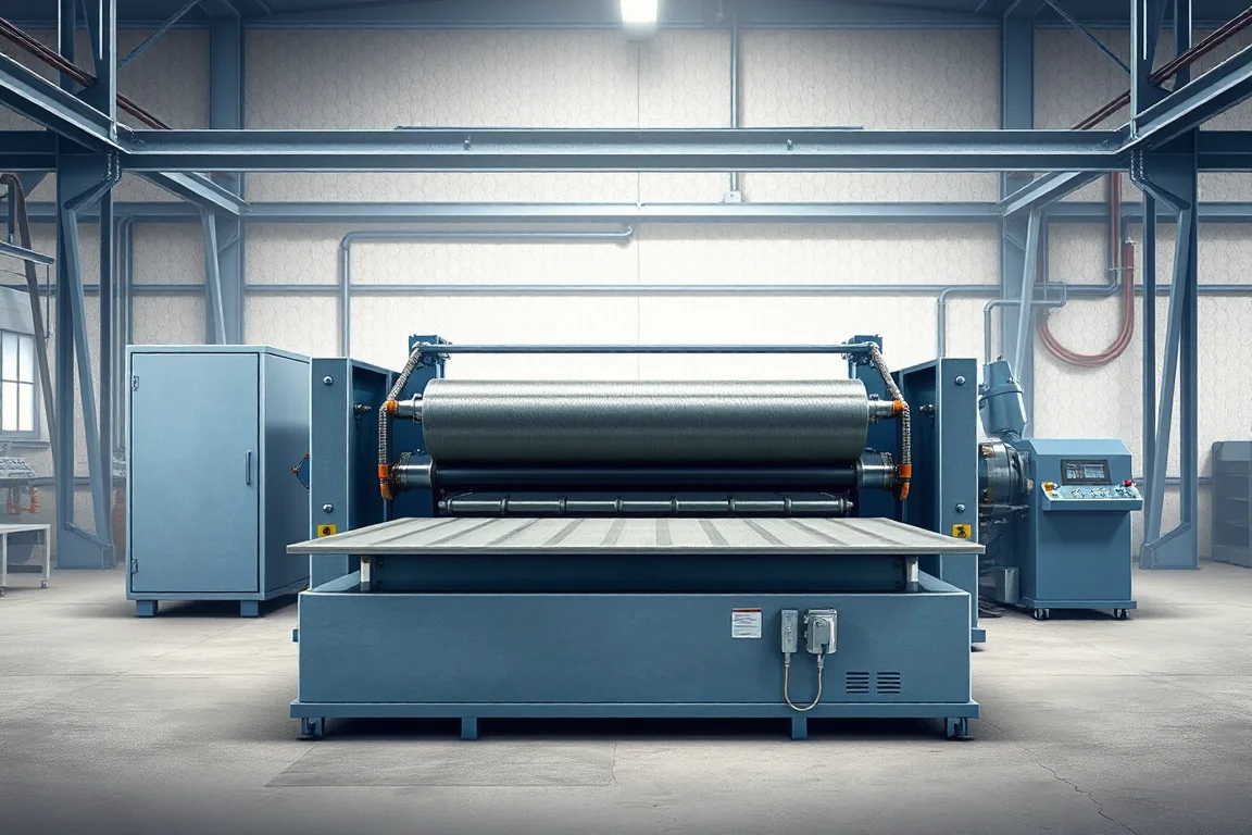
A cable tray roll forming machine produces the metal channel sections used by a specified cable-support system. Its product may have a solid or perforated base, formed side walls and returns or edges that connect with lids, couplers and fittings. Those interfaces turn a simple-looking tray into a coordinated product family.
The equipment should be selected around the actual catalogue: widths, side heights, materials, perforation patterns and joining details. A width-adjustable former can be valuable, but only when the associated punching, cutting and handling arrangements support the same range.
Which cable-support product is intended?
Separate sheet-metal trays from cable ladders, wire-mesh systems and enclosed trunking. They use different constructions and manufacturing routes. A formed tray body does not automatically include ladder rungs, a wire-welding process or a matching enclosure lid.
Within the tray family, identify solid-bottom and perforated variants, side-edge construction and the required couplers. The product name alone does not define which surfaces support cables, how sections join or whether a lid is fitted.
What should the tray drawing include?
Show the finished internal or usable width, side height, bend radii and top-edge details. State which dimensions are measured internally and which externally. Include the base and side-wall feature patterns with references to the cut ends.
- Base width and side-wall geometry.
- Returns, hems or lid-engagement edges.
- Perforations and connection holes.
- Material grade, thickness and finish.
- Section lengths and coupler arrangement.
- Required bends, tees, reducers and other separately manufactured fittings.
A catalogue width is not a sufficient tool specification. Two trays with the same nominal size may differ at the top return or coupler interface, making their lids and fittings incompatible.
How does the coil-to-tray sequence work?
The route coordinates coil preparation, feature-making, forming, cutting and collection. Perforated products require particular attention to the relationship between the flat pattern and the finished bends. The actual order of operations depends on the proposed line.
- Identify and present the specified strip.
- Produce the required base, side or connection features.
- Develop the side walls and top-edge details progressively.
- Maintain the specified width and wall relationship.
- Cut the section to its ordered length.
- Inspect and collect accepted trays without spreading or crushing their edges.
Ask how feature positions are controlled across the width range. A forming system may adjust easily while its punching layout remains fixed, so both parts of the route must be reviewed together.
What does width adjustment really change?
A width-adjustable line can move the side-forming paths while retaining an agreed edge geometry. That does not necessarily change side height, return size or bend arrangement. Request a configuration matrix separating adjustable dimensions from tool-dependent dimensions.
For each width, identify input strip width, punch pattern, guides and cutoff settings. If the tray base contains repeated perforations, explain how the pattern accommodates the width change without placing holes in unintended bend or edge locations.
Demonstrate a wide-to-narrow transition and recovery to the original setup. Include the first accepted tray, coupler or lid fit and inspection time. A quick powered movement is only one part of a useful product change.
How should perforation requirements be specified?
Provide the complete pattern rather than a photograph of perforated sheet. Hole or slot shape, spacing, edge distances and location relative to bends affect the punching route. Connection features near the ends may need a different control relationship from a repeating base pattern.
Inspect the formed product for burrs, distortion and feature position. Perforations can influence how the strip behaves during forming, so a trial on solid strip is not enough for a perforated catalogue. Use the actual pattern and material during the representative run.
Scrap removal and tool access deserve explicit scope. The line should manage punched waste without allowing it to damage the product or obstruct routine production. Maintenance and physical adjustment must follow the equipment maker's safe procedures.
How should material and finish be selected for the line?
Specify grade or alloy, thickness, coating and width as combinations. Galvanized steel, stainless steel and aluminum require their own review rather than being treated as equivalent because the finished tray shape is similar. The tooling and surface-handling arrangement must suit the actual catalogue.
Define whether finishing occurs before or after fabrication and which checks are required at the final stage. Keep material identity linked to the order and bundles. This helps distinguish similar products intended for different applications or finishing requirements.
Inspect cut and punched edges as well as broad surfaces. Cable-contact areas and mating edges need the condition specified by the product design; a clean-looking outside wall alone does not establish an acceptable tray.
Why are couplers and lids part of the trial?
A tray section must join its intended neighbor and, where specified, accept its cover. The coupler and lid can depend on small return dimensions or hole references that are not obvious from overall width. Supply production-intent mating components during tooling review.
Join several sections and fit representative lids using the intended method. Check the ends, side alignment and engagement along normal lengths. Record unplanned force, spreading or local trimming instead of treating a modified assembly as a successful unqualified result.
Keep mechanical manufacturing fit separate from electrical or load-performance requirements of the complete cable-support system. Those need the applicable product design and verification, not inference from the fact that two trays bolt together.
What fittings remain outside a straight-tray line?
Horizontal bends, vertical changes, tees, crosses and reducers may require separate blanking, bending, joining or fabrication. Identify the intended fitting catalogue and decide which parts are made in-house. A straight roll-formed tray is not a complete routing system by itself.
The same applies to lids and dividers. They may use related material and equipment concepts, but their profiles and feature patterns need separate scope. Listing them early prevents missing tooling or secondary operations from appearing only after the main line is installed.
How should collection and nesting be arranged?
Define stack orientation and bundle size for the tray widths and side heights. Nesting can reduce space but should not damage top edges or make sections difficult to separate. Test the packed result after normal handling.
Provide a clear route for short sections, long sections and rejected parts. Similar trays with different thicknesses or perforation patterns need reliable labels. Order identification should survive collection and any downstream finishing process.
What determines accepted production output?
Use finished trays or completed bundles for a stated width, length, material and pattern. Punching can govern the cycle on one product, while cutting or collection governs another. A forming-speed figure obtained with punching disabled does not represent perforated-tray output.
Compare a repeat order and a mixed-width order. The first shows sustained running; the second reveals adjustment, coil preparation and inspection demands. Record accepted quantity and rejects separately so the comparison reflects usable production.
In quotations, include all width-specific tools, punching equipment, controls, cutoff, takeoff and gauges. Identify future height or edge variants separately from the widths already covered by adjustment.
What should acceptance document?
- Tray width, side height, radii and top-edge geometry.
- Finished perforation and connection-feature positions.
- Length, end condition and edge quality.
- Coupler, adjoining-section and lid fit where required.
- Required width changes and repeatable recovery.
- Nesting, labels and packed-product condition.
- Accepted output with actual feature operations active.
Keep the setup, material and reference assemblies together in the production record. This gives operators a concrete basis for recognizing a later change in fit or geometry.
Frequently asked questions
Can one line make every tray width?
Only the agreed width range and associated patterns are supported. Side height and return geometry may remain fixed or require tools. Review the complete configuration matrix rather than a width range alone.
Can the same line make solid and perforated trays?
A configured route may cover both, but punching and forming must be demonstrated for the actual products. A solid-strip trial does not establish the behavior of a heavily perforated pattern.
Does the machine also make cable ladders?
Not automatically. Ladders contain separate rails and rungs with an assembly route. A tray line can be part of a wider equipment project, but the ladder components and joining operations require explicit scope.
Are lids included with tray tooling?
Only if their separate profile and production route are specified. Include the cover drawing and mating trial. A tray edge designed for a lid does not mean the same tools manufacture that lid.
Why inspect burrs after forming?
The delivered tray is the final inspection object, and forming or handling can change local edge condition. Check the relevant cable-contact and mating surfaces rather than relying only on the flat punched strip.
What information makes a quotation useful?
Provide tray and lid drawings, perforation patterns, material combinations, widths, heights, lengths and fittings scope. Add order mix and packing requirements. This defines the complete cable-tray production task.

Continue your research
- Cable Tray Roll Forming Machines
- Cable Ladder Roll Forming Machine
- Cable Trunking Roll Forming Machine
- Solid Bottom Cable Tray Roll Forming Machine
- U Channel Cable Tray Roll Forming Machine
- Cable Support Channel Roll Forming Machine
- How Cable tray roll forming machine Works
- How To Choose a Cable tray roll forming machine
- Cable tray roll forming machine Price: What Affects the Cost?
Configuration & specification inputs
Match the configuration to your section drawing, material and production requirements.
| Parameter | Requirement / confirmation needed |
|---|---|
| Profile geometry | Tray base, side walls, top returns and lid/coupler interfaces |
| Material | Specified grade or alloy, finish and fabrication route for each tray family |
| Thickness & grade | Approve actual material, thickness and width combinations |
| Process route | Coil preparation, required features, side and edge forming, cutoff and collection |
| Cutting | Preserve end holes, walls and top-edge fit through cutoff |
| Output | Accepted trays with actual patterns, width changes and normal nesting included |
| Electrical supply | Confirm utilities for the selected punching, adjustable forming, cutting and handling package |
| Acceptance | Measure section and features, fit couplers and lids, and verify width recovery and packed condition |