
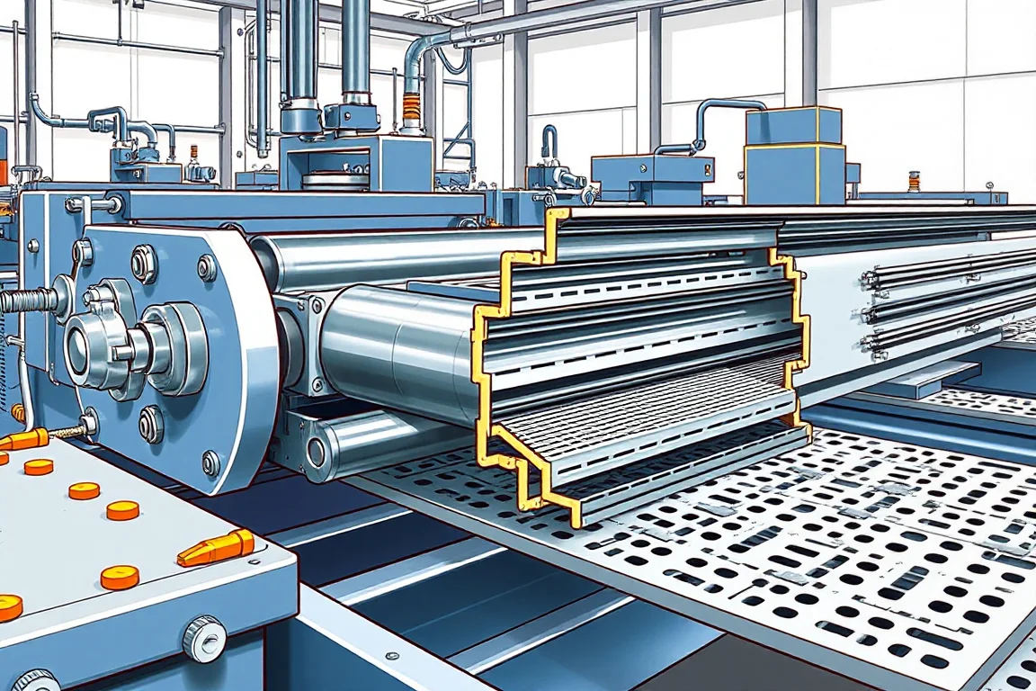
Roller, tooling and forming design for a cable tray roll forming machine is the engineering decision set that converts a flat strip into a functional tray section with stable bends, correct mating geometry and acceptable edges. It covers the number and order of forming passes, the shape of each roll, how the strip is guided, how springback is managed, and how punching, cutoff and cover engagement are integrated. A roll count alone does not describe quality; the forming design and the material it must accept matter more.
What roller and tooling design actually controls
Tooling design controls where the strip is located during each pass, how each bend is initiated and completed, and which surfaces remain free for perforation or edge return. The finished shape is not created in one station: it accumulates. If a bend is over-formed early, later passes may distort an adjacent flange. If it is under-formed, the final section may not close to the intended side height or base width. Good design keeps the strip located by features that will not be damaged, such as the base or a controlled edge, and sequences returns so that they do not interfere with punching.
Start from functional geometry, not roll count
Begin with the finished tray: base width, side height, return edge, perforation pattern and cover fit. These are functional interfaces, not cosmetic dimensions. A perforated tray and a solid tray may share a base width but demand different tooling because the punch pattern changes strip stiffness and local buckling risk. A ladder system is not simply a tray with larger openings; rails and rungs may be produced and assembled differently, and rung production can sit outside the rail-forming line.
How the forming sequence and interfaces work
A typical sequence runs from payoff through leveling, perforation or punching, side forming, cutoff, and then cover or assembly checks. Each interface has a job. Leveling prepares flatness and removes coil set so the strip enters forming predictably. Punching establishes holes before or after certain bends, depending on whether the holes would distort during forming. Side forming develops the base, sides and returns in stages. Cutoff separates the finished length and must support the profile and end quality. If the cutoff cannot handle the full range of sizes, the line may produce good sections but poor ends.
Perforation sequence and edge returns
The order of perforation relative to edge returns is a design decision with visible consequences. Forming a return before punching can stiffen the strip in a way that changes hole location or causes distortion around the holes. Punching before a return can be easier on the die, but later forming may pull the strip and shift pitch. The practical requirement is to inspect perforated parts around the holes after forming, not only at the punch station. If the intended design needs consistent hole position relative to the edge, the tooling must locate the strip from a feature that remains stable through the remaining passes.
Width adjustment and cutoff compatibility
Width adjustment can be handled by moving roll assemblies, changing spacers, or using dedicated tooling sets. Each approach changes setup time, repeatability and the risk of an undocumented adjustment. The cutoff must be checked against every size the line is expected to run: a cutoff that supports one base width may not support a wider or narrower section without changing blades or die geometry. If covers are required, cover fit depends on side height and return geometry, so cover engagement should be part of the forming design rather than an afterthought.
Selection decisions and tradeoffs
Comparing alternatives means comparing what each choice does to output and changeover. More forming passes can reduce strain per pass and make bends more gradual, which can help with material variation, but more passes mean more tooling, more setup points and more maintenance. Fewer passes can be simpler and faster to change, but may demand more from each roll and leave less margin for springback or thickness variation. Adjustable-width designs offer flexibility at the cost of alignment discipline; dedicated tooling sets offer repeatability at the cost of inventory and changeover time. A design that accounts for material variation and provides access to the final section is generally easier to keep in production than one that relies on exact strip behavior.
Material, thickness and springback
Tooling responds to the specified material and base-metal thickness, but the operating range requires supplier verification. Galvanized steel, stainless steel and aluminum behave differently in forming: they recover differently after bending, and they may need different roll clearances or bend radii. Springback is not a single number; it depends on material, thickness, bend radius and how the bend is constrained. The design should explain how bends develop, which surfaces locate the strip, and how springback is addressed. A design that assumes one material condition may not tolerate the variation present in production.
Acceptance checks before production release
Acceptance should check base width, side height, burr condition and cover engagement. Perforated parts need inspection around holes after forming. These checks confirm the forming design, not just the machine. They should be performed on the agreed material and profile extremes. If a dimension is out, the evidence should point to a specific pass or interface rather than prompting a general adjustment. Load rating and electrical continuity depend on the complete system and its verification, so they sit outside what roll tooling alone can demonstrate.
Practical checklist for reviewing a design
- Identify functional dimensions and mating parts, including cover interfaces.
- Review punch and cutoff tooling together with the roll tools, not separately.
- Confirm how the strip is located in each pass and which surfaces stay free.
- Check the sequence of edge returns relative to punching and perforation pitch.
- Ask how springback and material variation are handled.
- Verify tool changes using the agreed material and profile extremes.
- Keep the accepted setup and tool identification together so production does not depend on an undocumented adjustment.
- Confirm the cutoff supports all sizes and end quality requirements.
Keeping production repeatable
Repeatability comes from documented setup and tool identification, not from operator memory. When a roll set is changed, the accepted setup should travel with the tool identification so the next run starts from a known state. This is especially important when width adjustment or perforation pitch changes are part of normal production. If adjustments are made without recording them, the line may run acceptably today and unpredictably tomorrow.
FAQ: roller and tooling design questions
Does a higher roll count mean better forming?
No. Roll count is a consequence of how bends are distributed and how much strain each pass can tolerate. A design with more passes may be gentler, but it also adds setup and maintenance points. The useful question is how the bends develop and whether the design accounts for the specified material and thickness.
How does perforation pitch change with different tray sizes?
Pitch changes because the strip length between holes and the formed length differ after bending. If the design requires a specific pitch in the finished tray, the tooling must account for the stretch or compression that occurs during forming. This is why perforated parts should be inspected around the holes after forming, not only at the punch.
Can one machine run multiple base widths and side heights?
It can if the tooling and cutoff are designed for that range. Adjustable-width designs or dedicated tooling sets each have tradeoffs. The cutoff must support every size, and cover fit must be checked across the range. A single machine rating does not prove the full range is supported.
Why does cover engagement matter to forming design?
Cover engagement depends on side height, return geometry and how consistently the section forms. If the forming design does not control those features, covers may fit some sections and not others. Cover fit should be part of the original forming specification, not a separate assembly problem.
What evidence should a supplier provide about springback?
The supplier should explain how bends are constrained, which surfaces locate the strip, and how the design accommodates material variation. A claim that springback is handled without describing the mechanism is not useful evidence. The design should be reviewable pass by pass.
How should tool changes be verified?
Tool changes should be verified using the agreed material and profile extremes, with the accepted setup recorded alongside the tool identification. Verification should check base width, side height, burr condition, cover engagement and perforated areas. If a change is not recorded, the next setup may not repeat the accepted result.
Continue your research
- Cable Tray Roll Forming Machines
- Cable Tray Roll Forming Machine
- Cable Ladder Roll Forming Machine
- Solid Bottom Cable Tray Roll Forming Machine
- U Channel Cable Tray Roll Forming Machine
- Cable Support Channel Roll Forming Machine
- How Cable tray roll forming machine Works
- How To Choose a Cable tray roll forming machine
- Cable tray roll forming machine Price: What Affects the Cost?