
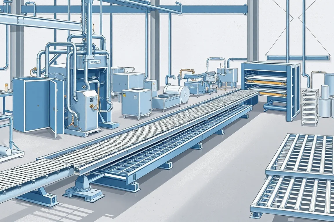
A cable tray roll forming machine turns flat steel coil into continuous lengths of cable tray, complete with sidewalls, returns, perforations, and cut-to-length ends. The machine does not simply bend metal; it coordinates strip feeding, punching, progressive forming, and cutoff so that each tray section matches the drawing before it leaves the line. Understanding how these stages interact helps buyers and operators evaluate a line for specific tray widths, materials, and production rates.
Defining Tray, Trunking and Ladder
Cable tray is an open, rigid structure that supports and routes cables. It typically has a flat bottom and raised sidewalls with a return flange. The tray may be perforated for ventilation and cable tie access, or solid for physical protection. Trunking is an enclosed system with a lid or cover that closes over the cables, offering more complete environmental separation. Cable ladder consists of two longitudinal rails connected by rungs, used where cables need frequent support or where air circulation is important. Each product type follows a different forming route on a roll forming line, although they may share coil handling and cutoff equipment.
Reading the Tray Drawing for Machine Setup
Before any coil is loaded, the tray drawing defines material thickness, strip width, bottom profile, sidewall height, return flange dimensions, perforation pattern, and end treatment. The strip width must account for the developed length of the entire cross-section, not just the visible bottom. For a hypothetical drawing example, a tray with a 100 mm bottom, two 50 mm sidewalls, and two 10 mm returns requires a strip that can form those features after accounting for bend allowances. The drawing also specifies hole diameter, pitch, and edge distance. These values determine punch tooling and station layout. A machine that cannot accommodate the required strip width or hole pattern will not produce the tray as designed.
Coil Entry and Strip Preparation
Production begins with a steel coil mounted on a decoiler. The strip is threaded through a straightener or leveler to remove coil set, then fed into the roll forming line. Proper strip preparation is critical because residual curvature can cause tracking errors and uneven sidewall heights. Some lines include a strip accumulator to allow continuous operation during coil changes. The operator must verify that the coil width and thickness match the drawing, and that the strip edges are straight. If the strip is not flat and aligned, every downstream station will amplify the error.
Punching Location and Perforation Workload
Perforations are created either before or after forming, depending on line design. In a pre-punch configuration, a punch press or die set punches the flat strip at high speed. This is common for simple hole patterns and allows high throughput. In a post-punch design, holes are punched after the tray is formed, which can be useful when holes must align with formed features. Perforated trays require more punching capacity than solid trays because the pattern repeats along the entire length. The workload depends on hole density, strip speed, and press tonnage. A line intended for perforated tray must have a punch system sized for the cutting perimeter engaged per stroke, material and thickness, tool arrangement, stroke demand and scrap removal, otherwise production speed drops or punch life shortens. Solid-bottom trays omit the specified bottom-perforation pattern but can still require side, fixing or end-connection holes. Their feature-making scope must follow the drawing.
Progressive Sidewall and Return Forming
After punching, the strip enters the roll forming stations. Each station performs a small amount of bending, progressively shaping the sidewalls and return flanges. A typical sequence might start with edge pre-bending, then gradually raise the sidewall to 90 degrees, then form the return. The number of stations depends on the complexity of the profile and material thickness. Thin, narrow trays may need fewer stations; deep sidewalls with tight returns require more stations to avoid cracking or distortion. The rolls must be set to the correct gap and alignment. If a station is misaligned, the tray can twist, bow, or develop wavy edges. The return flange affects stiffness and the cable-contact edge; its actual geometry and finished edge condition still require inspection. Safe edge returns are folded inward or outward according to the drawing, and they must be formed without sharp burrs that could damage cable insulation.
Cutoff and End/Joining Features
Once the tray profile is fully formed, a cutoff press shears the continuous length to the required dimension. The cutoff can be a simple shear or a combination tool that also punches end joining holes. Many tray systems use splice plates or couplers that require holes at specific locations near the ends. If the line includes an end punch, it must synchronize with the cutoff to place holes accurately. After cutoff, the tray ends may be deburred or chamfered to remove sharp edges. The finished tray is then ready for stacking or further processing. The cutoff station must be robust enough to handle the material thickness and production rate without causing deformation at the cut.
Cover Forming as a Separate Scope
If the tray requires a cover, it is typically produced on a separate roll forming line or a dedicated section of the same line. Covers are usually simpler profiles: a flat sheet with edge returns that snap or fasten over the tray sidewalls. Cover forming involves its own decoiler, straightener, forming stations, and cutoff. Trying to form covers on a tray line without dedicated tooling can lead to poor fit and wasted material. Buyers should clarify whether the machine is intended for tray only, cover only, or both, because the tooling and line layout differ significantly.
Width Changes Across the Complete Route
Changing tray width requires either changing the strip width and repositioning the forming rolls, or using a line with adjustable roll stations. Some machines allow width changes by moving side roll assemblies; others require changing entire roll sets. The width change affects the entire route: decoiler, straightener, punch, forming, and cutoff must all be reset. As a hypothetical size-change example, a line running 100 mm wide tray may need different guide settings than a 300 mm wide tray. If the line is not designed for quick changeover, width changes can take hours and reduce flexibility. The same applies to sidewall height changes, which may require different forming rolls or additional stations.
Accepted Tray Inspection and Handling
Finished trays should be inspected for dimensional accuracy, straightness, hole placement, and surface quality. A practical checklist includes: verify bottom width and sidewall height against the drawing; check that returns are formed to the correct angle and are free of cracks; confirm hole diameter and pitch; ensure the tray is straight within acceptable limits; and inspect for burrs or sharp edges. Trays should be handled with care to avoid bending or scratching. Stacking should use dunnage or separators to protect the profile. If trays are painted or galvanized, the handling system must avoid damaging the coating.
Process Map and Practical Comparison
The overall process map for a perforated tray line is: coil loading → strip straightening → pre-punching → progressive roll forming (sidewalls, returns) → cutoff → end feature punching → inspection. For a solid-bottom tray, bottom perforation may be omitted while specified side and connection features remain part of the route. For cable ladder, the process differs: two rails are formed separately, and rungs are inserted or welded in a secondary operation. Ladder lines often use a dedicated rung insertion machine rather than a continuous tray line. Strut channel production is different again: it forms a C-shaped channel with inturned edges and often includes a continuous slot punching operation. Strut output depends on its own material, return geometry, hole pattern and cutoff route; do not infer a higher rate from the product name.
A real comparison of alternatives: perforated tray versus solid tray. Perforated tray offers ventilation, easier cable tie anchoring, and lighter weight for the same material thickness, but requires more punching capacity and may be less rigid. A solid bottom offers a different enclosure and attachment arrangement. Structural and thermal suitability depend on the full tray design, cable installation and support conditions, not bottom type alone. The choice depends on cable type, environment, and support requirements. Another comparison: roll forming versus press brake production. Roll forming is continuous, faster for long runs, and produces consistent profiles. Press brake production is slower, suited to short runs or prototypes, and can handle complex shapes that are difficult to roll form. For cable tray, roll forming is the standard for volume production.
FAQ: What is the difference between a cable tray and a cable ladder?
A cable tray has a continuous bottom with sidewalls, while a cable ladder has two rails connected by rungs. Trays support cables along the bottom; ladders support cables on rungs, allowing more air circulation and easier drop-out. They are produced on different lines: trays use progressive roll forming, ladders use rail forming plus rung assembly.
FAQ: How does punching affect roll forming line speed?
Punching is often the bottleneck. The press must cycle for each hole or pattern, and the line speed must match the punch cycle. Dense patterns can increase stroke demand; assess tooling layout, engaged cutting perimeter, material, force and scrap handling. A larger or flying press is not the automatic solution. If the punch cannot keep up, the entire line slows down. Solid-bottom trays may have fewer bottom features but can retain other punching requirements, so compare the actual complete route.
FAQ: Why are safe edge returns important in cable tray?
Edge returns fold the sidewall edge inward or outward to manage the exposed edge; the finished condition must still be checked for sharp edges that could cut cable insulation or injure hands. They also add stiffness to the sidewall. Forming them correctly requires precise roll setup; if the return is too tight or too loose, it may crack or not provide the intended protection.
FAQ: Can one roll forming machine produce both tray and cover?
Usually not without dedicated tooling. Tray profiles and cover profiles have different cross-sections and require different roll sets. Some lines are designed with interchangeable roll stations or a separate cover line. Attempting to form covers on a tray line without proper tooling leads to poor fit and dimensional errors.
FAQ: What is the difference between cable tray and strut channel production?
Cable tray is an open-top, wide-bottom profile with sidewalls and returns. Strut channel is a narrower C-shaped profile with inturned edges and often a continuous slot. Strut channels use their own punching and forming arrangement; rate differences require trials on the specified material and feature pattern. They are not interchangeable without significant re-tooling.
Continue your research
- Cable Tray Roll Forming Machines
- Cable Tray Roll Forming Machine
- Cable Ladder Roll Forming Machine
- Solid Bottom Cable Tray Roll Forming Machine
- U Channel Cable Tray Roll Forming Machine
- Cable Support Channel Roll Forming Machine
- How To Choose a Cable tray roll forming machine
- Cable tray roll forming machine Price: What Affects the Cost?
- Materials and Thickness for Cable tray roll forming machine