
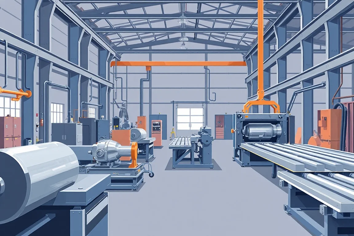
A custom profile roll forming machine progressively bends strip into a project-specific cross-section. The word custom refers to the finished part and production route, not a universal machine capable of making any shape. Understanding how the line works starts with the drawing, material and operations needed to turn the incoming strip into an accepted component.
Translate the finished part into a process brief
The component drawing defines the section, lengths, tolerances and functional interfaces. Add material grade or alloy, thickness, coating and any holes, notches or joins. These inputs establish whether the proposed route is a straightforward open profile or a more involved production system.
Separate constant cross-section requirements from local changes along the part. A long repeated section and a component with changing geometry present different process questions. Ask the equipment designer to identify what is formed continuously and what needs another operation.
Prepare and guide the incoming strip
Coil support and entry equipment bring the strip toward the forming section. The arrangement must suit the intended material and coil format. Strip width and edge condition matter because the finished bends and returns are developed from that input.
The entry route may include preparation or leveling according to the application. It should also establish a stable reference for later operations. Do not assume that every custom line uses the same entry equipment merely because the finished components are similar in size.
Develop the cross-section progressively
Successive roll passes change the strip shape toward the finished section. Each pass contributes to the overall development rather than making the final profile in one sudden bend. The sequence is designed around the geometry, material and practical access for later features.
Returns, narrow openings and asymmetric shapes require particular attention during development. The equipment proposal should explain how the important features will be produced and validated. A picture of the final section does not show the complete tooling sequence needed to make it repeatably.
Place feature operations where they can work
Holes, slots, embossments or notches may be made before forming, after forming or in a separate operation. The decision affects tool access, feature registration and the local condition after bending. Review the final feature datums rather than considering only where a tool can physically fit.
A line producing a blank channel is not a complete solution when the saleable part requires multiple features. Identify the equipment and tooling for those operations, and state whether they are integrated, supplied separately or excluded from the proposal.
Control the relaxed finished shape
The component must meet its drawing after it leaves the forming tools. Inspection should use the agreed support and measurement method so that the relaxed shape is evaluated consistently. Restrained measurements inside the process can be useful for setup but are not a substitute for finished-part acceptance.
Material variants can require different approved settings or tooling considerations. Keep the material and setup identity with trial samples. That connection helps distinguish a forming-sequence issue from a change in the strip supplied to the line.
Cut the profile without losing the required end condition
The cutoff divides the continuous section into the required lengths. Its arrangement must suit the profile and production route. Review cut quality, length control, end distortion and any requirements for later assembly or joining.
Representative short and long parts should be included in trials. Inspect both ends and compare them with the central section. A dimensionally correct continuous profile does not prove that the cut component will meet end-specific requirements.
Add joining and secondary work where specified
Some custom profiles are joined, curved, assembled or finished after forming. Those operations can change the final component and need their own equipment and acceptance scope. Mark the boundary between what leaves the forming line and what the customer ultimately needs.
Where downstream work is outside the supply contract, confirm that the formed part is suitable for that next step. Include the responsible party, interface requirements and sample validation in the project plan instead of leaving the handoff implicit.
Handle and identify the completed parts
Discharge supports, stacking and packaging should protect the features that make the custom section useful. A delicate return or cosmetic surface may need a different handling approach from a robust plain channel. Inspect the part after normal movement and packing, not only at the machine exit.
Identification becomes important when related variants look alike. Keep part numbers, drawing revisions and production batches connected to the output. A correct section sent under the wrong identity still creates a production or assembly problem.
Demonstrate the complete production cycle
A useful trial begins with production-intent material and finishes at the agreed acceptance boundary. It includes the required features, cuts and downstream work. Record accepted quantity, startup scrap, changeover work and any waiting between operations.
For shared equipment, demonstrate the actual transitions between relevant profiles. The time needed to exchange forming tools is only one part of recovery; feature tools, cutoff components and first-part approval can add important work.
Use the process map to clarify responsibility
Draw a simple sequence from incoming coil to packed component and identify who supplies each operation. This makes omitted tooling, utilities, handling and inspection easier to spot. It also allows proposals with different levels of integration to be compared on the same finished-part basis.
Keep unresolved geometry or material questions visible until trials or engineering review answer them. Custom roll forming is a defined production solution, not permission to assume that every feature can be added later without affecting the line.
Frequently asked process questions
Can a custom line make any profile?
No. Its capability is defined by the approved geometry, material and tooling range. New shapes may need additional tools, another process or a different equipment arrangement.
Are holes always punched before forming?
No. The suitable sequence depends on access, geometry and final feature requirements. Ask how the proposed route establishes and checks the finished datums.
Does a formed sample prove the complete line?
It proves only the operations and conditions represented by that sample. Include cutting, features, handling and any specified secondary work before accepting the complete route.
What is the most useful first document?
A controlled part drawing linked to the material and expected order mix. Add a list of required operations and identify any features or performance requirements that still need review.
Continue your research
- Custom & Industrial Profile Roll Forming Machines
- Custom Profile Roll Forming Machine
- Hat Channel Roll Forming Machine
- C Channel Production Line
- Z Channel Production Line
- Electrical Cabinet Frame Roll Forming Machine
- How To Choose a Custom profile roll forming machine
- Custom profile roll forming machine Price: What Affects the Cost?
- Materials and Thickness for Custom profile roll forming machine