
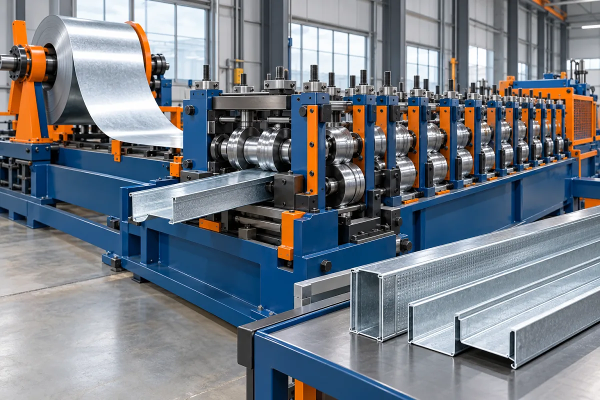
A stud and track roll forming line makes the paired metal sections used in a specified framing system. The stud usually includes the features shown on its lipped section drawing, while the matching track provides the intended receiving geometry. Production succeeds when those parts fit and carry the correct lengths and features, not merely when each resembles a channel.
Define the framing product before the process
Drywall components, structural framing members and more highly fabricated frame parts can have different material, feature and inspection requirements. Do not use the broad phrase light gauge framing as a complete product specification. Provide the relevant stud, track and connection drawings.
The equipment makes the specified component; it does not establish the wall's structural, fire or acoustic performance. Those outcomes depend on the complete approved assembly. Keeping this distinction clear helps the production brief focus on the geometry and material it must deliver.
Coil preparation supplies the correct strip
Payoff and entry equipment present the specified steel with its required width, thickness and coating. Record the material identity and the product configuration it serves. A coil appropriate for one stud family should not automatically be treated as approved for another structural or nonstructural product.
Use the developed strip width for the complete section. Web width alone omits flanges, lips and bends. The track may have a different development even when it is named for the same nominal framing size.
Feature operations are defined by the component drawing
Service holes, fixing features or specified embossing may be integrated into the route. Identify each feature's geometry and location, and ask where it is produced. A repeated service opening is not interchangeable with an arbitrary hole added later.
The feature pattern must remain suitable for the approved framing product. Do not assume that any convenient opening can be introduced without design review. The line's punching capability is a manufacturing function, not permission to change the member.
Forming develops the web, flanges and lips
Successive roll stages create the section. Stud and track tooling needs to preserve their intended relationship, including the receiving fit. Inspecting them independently against unrelated nominal dimensions can miss a pair that will not assemble as specified.
Where the machine offers adjustable sizes, identify the supported flange and lip combinations as well as web widths. A width change does not automatically provide every section variant. The approved product matrix should state what is actually supported.
Stud-to-track changes need a complete setup sequence
A combination line may produce both products using defined adjustments or change components. Ask which guides, forming references, feature settings and cutting parts change. The equipment label alone does not explain the transition.
Verify a mating pair after recovery. The first accepted stud and track should meet their drawings and fit in the intended assembly. A movement completed by the controls is not the same as accepted production.
Cutting establishes length and usable ends
The cutting route must deliver the specified lengths without unacceptable local deformation. Inspect ends for the agreed condition and confirm that they do not interfere with assembly. A central section coupon is not enough to verify this part of the process.
Short components can require many cuts and handling events, while longer members need suitable support. Include representative lengths in the demonstration so the production plan is not based solely on one convenient test piece.
Nesting and bundling are production operations
Finished sections need to be counted, protected and packaged in the intended commercial format. A fast former can wait on manual collection if the downstream route is not matched to it. Bundling capability should therefore be evaluated with the actual stud and track shapes.
Keep product size, material and quantity identifiable in the bundle. Similar-looking framing sections may serve different applications. Losing that identity can create an order error even when the physical forming quality is good.
Inspect the pair and its specified features
Where the order includes short bridging or another related framing component, identify its own production route and drawing. A stud-and-track line may support additional members within its defined configuration, but the relationship should be demonstrated rather than assumed from a shared material description.
Measure web, flanges, lips and length using the agreed references. Check service-hole or other feature positions on the final section. Assemble the stud and track in the defined manner and record any interference or unacceptable looseness against the product criteria.
Use the actual material and representative lengths. A short hand-adjusted sample does not demonstrate a stable production route. Retain identified first-off and continued-run samples when the acceptance plan requires them.
Follow a mixed order through release
A useful demonstration contains both members of the framing pair and a relevant size change. Count accepted, correctly identified pieces through the agreed packing boundary. Record rejects and interruptions separately.
- Confirm material and stud/track drawing revisions.
- Produce the required sections and feature patterns.
- Inspect dimensions, length and end condition.
- Verify the mating assembly.
- Check counts, labels and bundle condition.
- Repeat first-off checks after the required transition.
For example, a nominally matching pair may use different actual dimensions to achieve the intended fit. The machine should follow those controlled drawings rather than make both web dimensions identical because the commercial names match. This simple distinction prevents a common misunderstanding in procurement and first-off inspection.
Frequently asked stud and track process questions
Can the same nominal size be used as the only fit check?
No. The actual stud and track geometry and approved clearance relationship matter. Inspect the pair against its drawings and intended assembly.
Does every line make service holes?
Only if the required feature-making equipment and tools are included. Specify the pattern and final-member references rather than assuming holes are part of every standard package.
Are drywall and structural studs interchangeable products?
They should be treated according to their specified materials, geometry and applications. A similar channel appearance does not establish equivalent performance or approval.
Why include bundling in the process review?
It determines how accepted sections become countable, identifiable saleable packages. Poor downstream handling can constrain output or damage parts after successful forming.
Continue your research
- Stud & Track Roll Forming Machines
- Drywall Stud Roll Forming Machine
- Drywall Track Roll Forming Machine
- C89 Light Gauge Steel Framing Machine
- C140 Light Gauge Steel Framing Machine
- Top Hat Light Steel Framing Machine
- How To Choose a Stud and track roll forming machine
- Stud and track roll forming machine Price: What Affects the Cost?
- Materials and Thickness for Stud and track roll forming machine