
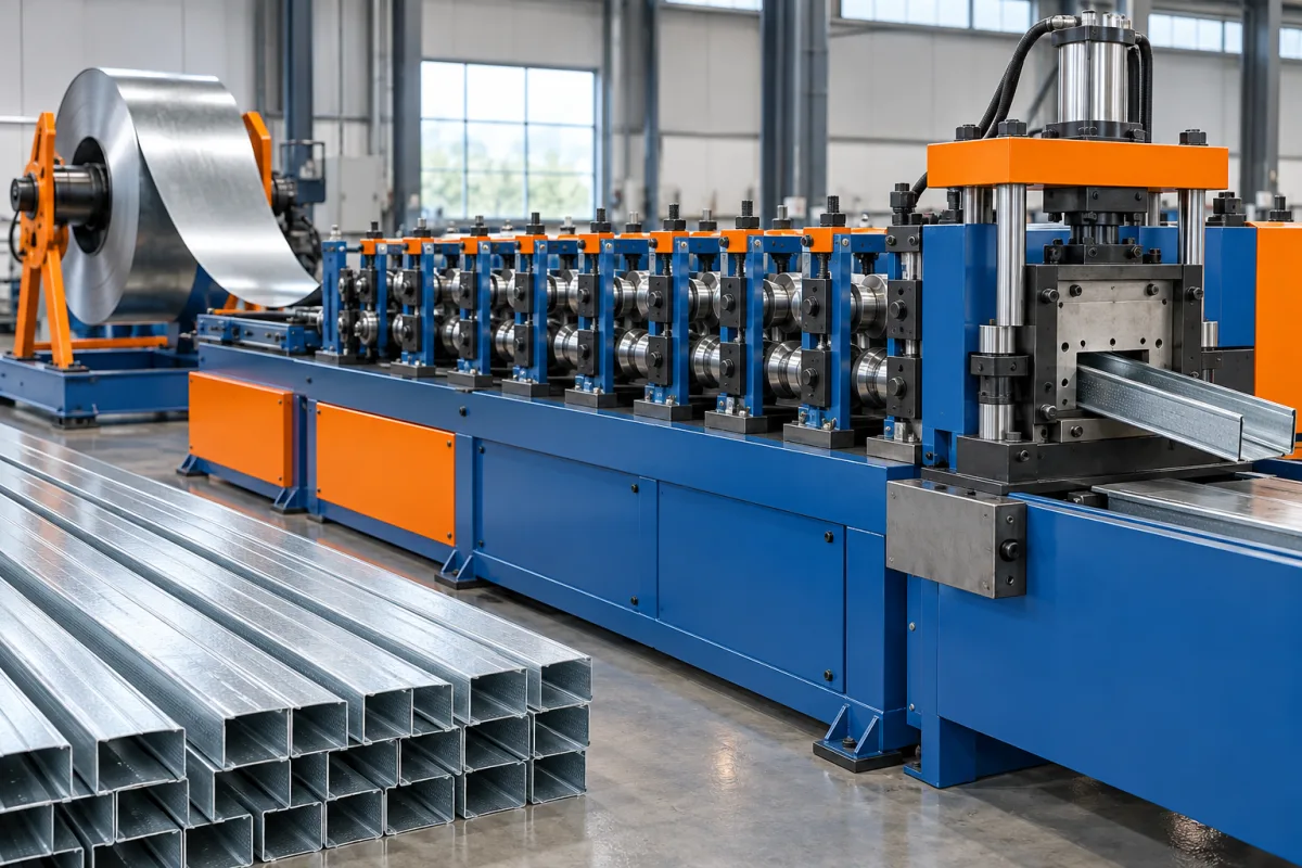
A drywall track roll forming machine makes the channel sections that locate compatible studs at the boundaries of a partition or lining. Track may look simpler than the lipped stud it receives, but its internal width, flange shape, straightness and end condition determine whether installation is straightforward or requires unwanted adjustment.
The right specification therefore begins with a stud-and-track interface. It also distinguishes ordinary track from special products such as deeper-leg, slotted or movement-accommodating designs. Those products can require different tools and feature operations even when the catalogue groups them under the same track heading.
What does a drywall track contribute to the wall?
The channel positions the studs and provides the connection defined by the wall design. It may be supplied in stock lengths for site cutting or in project lengths for organized assembly. Its commercial size usually relates to the associated stud family, but that label does not replace the actual dimensional relationship.
A track should not be selected from width alone. The wall design determines the required flange dimensions, fasteners and any movement provisions. Manufacturing equipment must reproduce that selected product consistently; it does not decide which partition connection is appropriate for a building.
How is track geometry different from stud geometry?
A common track has a web and two open legs, while its corresponding stud includes additional return lips. That distinction changes the forming sequence and the way the section behaves during cutoff and discharge. The track's functional opening must remain consistent along the finished length.
Specify inside and outside dimensions unambiguously. A stud fitted into a channel is sensitive to the combined material thicknesses, bend details and permitted clearances. Copying the stud's nominal width directly into a track drawing can produce a pair that looks compatible in a product list but does not assemble correctly.
- Identify the track's internal receiving width.
- Define each leg height and whether the legs are equal.
- Show bend radii and the surfaces used for measurement.
- State straightness, twist and end-condition requirements.
- Reference the stud and fixing arrangement used for fit approval.
Which track variants belong in the project scope?
Begin with standard unperforated track, then list every required variant separately. A deeper-leg channel changes more than a product name: it affects strip development, tooling, cutoff support and handling. Slots, fastening holes or special end details introduce additional operations and inspection criteria.
Movement-related tracks require particular care in the specification. Identify the actual engineered connection and its permitted use rather than describing any tall or slotted channel as a universal deflection track. The machine enquiry should include the relevant drawing and feature pattern without making assumptions about wall performance.
A useful scope matrix separates changes in width, leg height, material and features. This reveals whether one adjustable route is realistic or whether separate tools and production arrangements are needed for distinct track families.
How does the production sequence work?
Coil payoff and entry guidance establish a controlled strip path. The proposed line then performs any required punching, progressively bends the two sides, cuts the ordered length and supports the channel during collection. The position of cutting and feature-making should be specified rather than inferred from a generic machine photograph.
- Identify and load the coil within the agreed handling limits.
- Guide the strip through the required preparation and feature operations.
- Develop both legs through the forming passes.
- Control the receiving opening and the relationship between the legs.
- Cut the ordered length with support appropriate to the open channel.
- Inspect and group tracks without distorting their sides.
Ask how startup pieces and punched scrap are handled. A complete production arrangement includes these routine tasks, as well as access for safe threading and the removal of finished bundles.
What material information is needed?
Specify grade, base-metal thickness, coating, strip width and any important incoming condition. Group those values by product rather than combining unrelated maximums into an unrealistic envelope. The same track dimensions in a different material can require another setup and a fresh forming review.
Track often needs to fit studs made from a separately purchased coil. Acceptance should therefore use the agreed dimensional tolerances and representative mating products, not a pair specially adjusted to fit each other. Record coil identity with the measured samples so later assembly issues can be investigated systematically.
If a protective finish must survive forming and stacking without visible damage, define how it will be inspected. Look at bends, cut edges and contact points separately; they can reveal different sources of marking.
How should width and leg-height changes be evaluated?
A width-adjustable arrangement can support several receiving sizes, but its permitted combinations need to be explicit. Ask whether the legs retain one height, whether both sides move and how the cutoff follows the new section. Do not assume that a width control also provides an independent leg-height change.
For changes requiring tools, list the rolls, guides, spacers, feature dies and cutting parts involved. Demonstrate the complete transition through to a measured, accepted track. A changeover time that ends before inspection or tool recovery is not comparable with a first-good-product time.
When deciding between a dedicated track line and a shared stud-and-track machine, compare the actual order sequence. Frequent small track batches can interrupt stud production, while a shared route may be practical for a lower-volume catalogue with predictable scheduling.
Why does cutoff deserve a separate review?
An open channel can show local flare, collapse or end distortion if cutting and support are not suited to the section. Inspect the ends after ordinary discharge, and compare them with the middle of the same piece. A good mid-length cross-section does not prove that the delivered product will receive a stud cleanly near its end.
Specify the required shortest and longest lengths and demonstrate both. Short pieces create frequent cutting and collection cycles; long pieces require adequate support and room for removal. The proposed takeoff should keep those demands from being hidden behind an isolated forming-speed figure.
How can track fit be tested reliably?
Use production-intent studs and tracks with the approved drawings available. Assemble at several positions along the channel, including near the ends. Check whether the intended fit can be achieved without unplanned opening, squeezing or trimming of the track.
Record the measured receiving width, leg condition and any interference. If the assembly fails, distinguish track geometry from stud geometry and from an incorrect component choice. This is more useful than changing the track until one selected stud happens to fit.
For special tracks, include the specified connection components and feature positions in the check. Dimensional compatibility is a manufacturing result; the suitability of the complete wall connection remains tied to its approved design.
What handling and packing arrangements are useful?
Define how tracks nest, how many are bundled and how the open legs are protected during movement. Excessive packing force or poor support can alter a channel after it has passed inspection. Retain a simple check at the packing stage to distinguish forming problems from handling damage.
Labels should identify size, material, length and the relevant order or batch. Similar-looking tracks with different thicknesses or slot patterns should not become indistinguishable once nested. For project supply, agree the bundle sequence before choosing counting and labelling equipment.
What determines useful production output?
Measure accepted tracks or completed bundles over a defined order. Include cutting cycles, coil replacement, width changes and normal inspection. If perforated variants are part of the catalogue, test their actual pattern because feature-making may alter the complete production cycle.
Compare the equipment package on the same basis: payoff, tools, controls, punching where needed, cutoff, takeoff, gauges and commissioning. Identify future variants separately. A basic plain-track route and a multi-size slotted-track package should not be judged by their machine prices alone.
What should the factory acceptance checklist contain?
- Approved cross-sections, material combinations and corresponding stud references.
- Measurements of receiving width, legs, length and straightness.
- Inspection of cut ends, burrs and surface condition.
- Fit checks at representative positions along the track.
- Verification of holes or slots against the finished datums.
- A demonstrated size change followed by accepted production.
- Bundling, identification and output records for a representative order.
Retain the setup and samples used for approval. They provide a practical reference for operators when a similar order returns months later.
Frequently asked questions
Is track width identical to stud width?
The commercial names may correspond, but the actual mating dimensions need a defined clearance. Use the controlled drawings and intended measurement convention. Nominal labels alone cannot establish whether the assembled pair will fit.
Can ordinary track tooling make deflection track?
Only if the specified geometry and features fall within the agreed configuration. Taller legs, slots and special interfaces may require different tools. Start with the exact connection drawing rather than treating all movement tracks as one product.
Does a track line need punching?
That depends on the catalogue. Plain channels may not require it, while specified holes and slots need a defined production route. List those features and their positions before comparing equipment options.
Can one machine make both stud and track?
A configured shared line can do so, but the change parts and recovery process must be demonstrated. Removing a lip-forming function is not necessarily the only change. Include guides, cutoff and features in the comparison.
Why do accepted tracks sometimes become difficult to fit later?
Check whether packing or transport changed the legs, and confirm that the matching stud is correct. Compare retained samples and measurements before adjusting the production setup. A later fit issue is not automatically a forming fault.
What is the best starting brief?
Supply track and stud drawings, material combinations, lengths, required features and bundle arrangements. State the intended order mix. This turns a broad track-machine request into a clear production and acceptance specification.

Continue your research
- Stud & Track Roll Forming Machines
- Drywall Stud Roll Forming Machine
- Light Gauge Steel Framing Machine
- C89 Light Gauge Steel Framing Machine
- C140 Light Gauge Steel Framing Machine
- Top Hat Light Steel Framing Machine
- How Stud and track roll forming machine Works
- How To Choose a Stud and track roll forming machine
- Stud and track roll forming machine Price: What Affects the Cost?
Configuration & specification inputs
Match the configuration to your section drawing, material and production requirements.
| Parameter | Requirement / confirmation needed |
|---|---|
| Profile geometry | Track receiving width, leg heights, radii and stud interface |
| Material | Specify grade, coating and incoming-strip condition for each track family |
| Thickness & grade | Pair base-metal thickness with the approved track and stud drawings |
| Process route | Payoff, optional feature-making, leg forming, supported cutoff and nesting |
| Cutting | Check flare, crushing and burr condition at both ends |
| Output | Accepted track bundles including required slots, size changes and collection |
| Electrical supply | Size utilities from the selected feed, forming, feature and cutting package |
| Acceptance | Measure opening and legs, inspect finished features, and check fit along production-length tracks |