
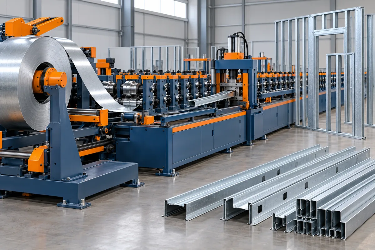
A light gauge steel framing machine converts specified coil into framing members with the geometry, lengths and features needed by a particular building system. The central production challenge is not simply making a C-shaped section. It is turning an approved member schedule into identifiable parts that fit their connections and can be assembled in the intended order.
Projects range from stock-length framing to building-specific kits. These require different combinations of software, punching, marking, forming, cutting and handling. A useful equipment brief describes the finished kit and the information that drives it, then works backward to the machinery needed to produce it.
Which framing production model is intended?
A stock-product business produces standard members for distribution and site fabrication. Its priorities may include dependable sizes, economical coil changes and efficient bundles. A project-based framing operation produces members linked to positions in panels, trusses or other assemblies. Feature locations and part identity become especially important.
A third arrangement supplies partially assembled frames rather than loose members. In that case, the former is only one part of the factory. Assembly tables, fixtures, fasteners, inspection and finished-panel handling need their own space and process definition. A member-making line should not be confused with a complete building-panel manufacturing plant.
How should the section family be defined?
List the cross-sections used by the framing system, including studs, tracks, blocking and any special members. Specify which dimensions change and which remain fixed. A catalogue of several widths sharing one flange and lip arrangement differs from a set of unrelated sections.
For each family, provide the web, flange, lip, radii and relevant joining interfaces. If members overlap, nest or pass through another section, show that relationship. The tooling review needs the assembled condition as well as the loose cross-section so that local features are not designed in isolation.
- Controlled member and connection drawings.
- Material combinations and thickness conventions.
- Length limits and end details.
- Feature schedule with datums and permitted positions.
- Part identification and required production records.
- Assembly and inspection responsibilities.
What information travels from design to the machine?
Define the boundary between structural design, detailing and machine control. Structural calculations establish the framing requirements; detailing creates the manufacturable member information; the controller executes the approved production instructions. Combining those activities in a sales description does not make them the same responsibility.
Ask which file formats or interfaces are supported, which dimensions and features transfer, and how errors are detected before production. Demonstrate a representative project containing several lengths, mirrored or repeated members and the relevant feature types. A simple straight member is not enough to prove the full workflow.
Revision handling also matters. The production team needs a clear way to distinguish a released member list from a superseded one and to identify parts already made. This is a practical shop-floor requirement even when the wider content or business system deliberately avoids complicated approval workflows.
Which feature operations belong in the line?
The framing design may require service openings, fixing holes, notches, dimples or local reliefs. Include only the operations actually required, and show their relationship to the finished section. Similar-looking features can have different functions, so their names should not replace drawings.
Review combinations as well as individual operations. A hole close to a cut end or another feature may create a different production constraint from the same hole in an open area. Ask how the proposed tooling handles the required minimum separations and how the control system prevents unsupported combinations.
Inspect features after forming and cutting. Their final position, condition and accessibility in the assembly are more important than a successful punch stroke on flat strip. Scrap removal and tool access also belong in the practical equipment review.
How does the complete manufacturing route work?
- Job preparation: confirm the released member data, material and part-identification scheme.
- Coil preparation: load the specified strip and establish its identity in the production record.
- Feature-making and marking: perform the required operations in the sequence supported by the line.
- Progressive forming: develop the approved section while preserving its functional interfaces.
- Cutoff: produce the required ends and lengths without unacceptable local distortion.
- Sorting: identify and group members by the agreed kit or assembly sequence.
- Assembly and checking: confirm fit and completeness using the applicable fixtures and drawings.
The order of specific machine operations can vary. Evaluate the actual proposed layout and control logic instead of assuming that every framing line follows an identical arrangement.
What material range should be tested?
Specify grade, thickness, strip width and coating together. Framing applications can place different demands on the same nominal section, and a change in material response can affect bends, springback and feature quality. The trial matrix should represent the combinations the factory intends to produce.
Keep the material identification connected to the member or bundle record. If an assembly later shows unexpected fit, the team should be able to compare its coil, drawing revision and setup with the acceptance reference. Traceability is most useful when it supports a concrete investigation rather than producing unused paperwork.
Do not substitute a convenient coil for the agreed trial material without recording the difference. A good demonstration on one stock does not establish the production result for every grade or thickness in the commercial proposal.
How should software-driven flexibility be judged?
A control interface can change member lengths and supported feature positions without making the physical tooling universal. Different webs, flanges, lips or connection shapes may still require mechanical changes. Request a clear matrix separating programmable variation, adjustable dimensions and tool replacement.
Test an actual change of job, not merely a screen preview. Confirm the resulting part marks, feature positions, cut lengths and grouping. Then return to an earlier job and inspect the first recovered parts. This shows whether the production workflow is repeatable under realistic scheduling.
Where does kit accuracy depend on handling?
A correctly formed member loses much of its value if its identity is missing or it is delivered in the wrong bundle. Decide where marks appear, whether they remain readable during assembly and how short or similar-looking parts are kept distinct. Labels and printed marks should support the assembly method, not obstruct it.
Provide room for completed kits, rejected parts and rework decisions. Mixing those flows can make a production count look correct while leaving an incomplete frame at the assembly station. A kit-completeness check is often more useful than a total metre counter alone.
How should output be measured for a framing project?
Use a representative member list with its actual lengths and feature density. Record accepted parts, complete kits and the time required for changes, inspection and collection. A long unpunched member and a short feature-intensive component can produce very different practical cycles.
For a planning example, a panel needing 12 studs, two tracks and four blocking pieces requires all 18 accepted parts before its loose-member kit is complete. Producing extra studs does not compensate for missing tracks. Evaluate the line and sorting process against complete assemblies as well as aggregate material length.
What should an acceptance project demonstrate?
Select a manageable but representative assembly containing the important section and feature combinations. Freeze the drawings, data files, material and measurement method before the trial. This gives both sides a common reference for identifying deviations.
- Import the agreed member data without unrecorded manual corrections.
- Produce and identify every required part.
- Measure sections, lengths and feature positions against their datums.
- Check cut ends and surface condition.
- Assemble the representative frame with the specified connections.
- Record missing, rejected and replaced parts separately.
- Repeat a relevant job or size change and verify recovered production.
Assembly fit and manufacturing accuracy do not replace the engineering verification of the building system. Keep those responsibilities clear in the project scope while ensuring that the machine trial produces meaningful, usable evidence.
Frequently asked questions
Does the machine design the building?
Not by virtue of being a framing machine. Structural design, detailing and production control have different roles. Confirm the software package and responsibility boundaries explicitly, including who releases the member information for manufacture.
Can it make both walls and roof trusses?
A suitable system may produce members for several assemblies, but the section, connection and feature requirements must be reviewed. A shared material or C-shaped outline does not prove that all required parts fit the same tooling.
Is a faster line always better for project kits?
No. Feature operations, sorting and assembly preparation may govern the useful rate. Compare complete accepted kits from the same member list rather than an uninterrupted strip-speed demonstration.
Why are part marks important?
They connect a physical member to its position in the assembly. Repeated lengths or mirrored feature patterns can otherwise be confused. Choose a marking and bundle method that remains usable through handling and installation.
Can every dimension change through software?
Only dimensions and features supported by the physical configuration. Web changes, flange changes and new connection shapes can require adjustment or replacement tools. Ask for an explicit capability matrix and demonstrate the needed transitions.
What is the best enquiry package?
Provide section and connection drawings, material specifications, a representative member file and the intended assembly workflow. Add marking, bundling and acceptance requirements. This makes the proposal about a working framing process rather than a former alone.

Continue your research
- Stud & Track Roll Forming Machines
- Drywall Stud Roll Forming Machine
- Drywall Track Roll Forming Machine
- C89 Light Gauge Steel Framing Machine
- C140 Light Gauge Steel Framing Machine
- Top Hat Light Steel Framing Machine
- How Stud and track roll forming machine Works
- How To Choose a Stud and track roll forming machine
- Stud and track roll forming machine Price: What Affects the Cost?
Configuration & specification inputs
Match the configuration to your section drawing, material and production requirements.
| Parameter | Requirement / confirmation needed |
|---|---|
| Profile geometry | Controlled framing sections with connection datums and required member features |
| Material | Project-specified framing grade and coating linked to member or bundle records |
| Thickness & grade | Approve actual grade, thickness and width combinations |
| Process route | Released member data, traceable coil, feature-making, marking, forming, cutoff and kit sorting |
| Cutting | Coordinate finished ends and lengths with the member data and assembly references |
| Output | Complete accepted member kits from a representative feature-intensive job |
| Electrical supply | Confirm utilities for the specified former, feature tools, marking and handling equipment |
| Acceptance | Import a trial job, inspect and identify every part, assemble the reference frame and demonstrate repeat production |