
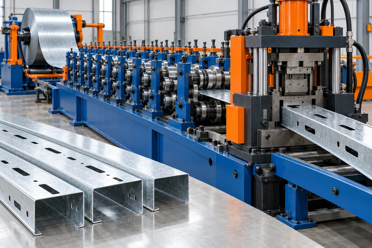
A C140 light gauge steel framing machine enquiry refers to a C-shaped framing family commonly identified by a nominal 140 mm web. The deeper web distinguishes it from a C89 family, but it does not define the flange, lip, material or connection details. The machine must be specified for the complete framing system and the member data it will receive.
The useful outcome is not simply a deeper channel. It is a set of correctly formed, featured and identified members that fit their approved assemblies. That requires coordination between the section drawing, project information, punching operations and finished-part handling.
What must be confirmed about the C140 section?
State the web dimension and measurement datum, then add flange widths, lips, radii and any special assembly geometry. Identify tracks, connectors or mating members that control fit. A nominal 140 label should never replace the cross-section drawing.
Record each approved material combination with the section. A deeper web is not, by itself, evidence of a particular load capacity or building application. Those decisions remain part of the structural system design.
What changes when moving from C89 to C140?
The developed strip width and forming geometry change, and feature positions may change with them. Tooling, guides, punch layout and cutoff support need review. Existing project data may also refer to a different section library or connection detail.
If both families are required, ask for an explicit multi-profile scope. Identify replacement tools and the complete changeover sequence, then demonstrate an accepted assembly after conversion. A web adjustment alone does not establish compatibility with the second framing system.
Which features should the machine produce?
Define service openings, connection holes, slots, notches and end preparation from approved member drawings. State their positions from final member datums and cut ends. Include any features required for the actual assembly method rather than copying a generic tooling list.
- Separate connection features from service openings.
- Identify orientation on web and flanges.
- Show protected or unmodified connection zones.
- Specify member identity and assembly references.
- Record any secondary operations outside the line.
The feature schedule should be checked against the intended structural design. Manufacturing convenience is not a basis for moving or enlarging openings.
How should the design-to-production workflow operate?
Define how approved member data becomes a production program and how revisions are controlled. The program should preserve units, section identity, handedness, lengths and feature positions. Operators should be able to connect a finished part to its project and drawing.
Use a representative assembly to test that data path. A file may import successfully while still containing a wrong orientation or outdated feature pattern. Physical first-piece and assembly checks are needed before a large run.
What should be included in the forming route?
Coil preparation supplies strip to the specified feature-making and progressive forming operations. The C140 web, flanges and lips are developed, the member is cut to length and its identity is retained through discharge. The actual sequence should be explained in the equipment proposal.
Review access for features and support at cutoff. A larger web can change the way the member passes through those operations. Trial the actual section instead of assuming experience with a shallower framing profile covers the same arrangement.
How should material and dimensional quality be assessed?
Run the intended grade, base-metal thickness and coating. Measure web, flange, lip and angle dimensions on agreed supports. Inspect straightness, twist, feature edges and local end condition as separate items.
Keep material identity with the trial record. Where several thicknesses are intended, select representative cases across the proposed range. Do not infer the whole envelope from one convenient coil and one unfeatured sample.
What does a useful assembly trial look like?
Produce members for a small real frame or connection group containing typical lengths, intersections and service features. Confirm labels and orientation, then assemble using the specified method. Record any extra trimming, forcing or feature correction.
Compare the completed assembly with its approved references. This tests more than loose-section accuracy: it reveals whether data, feature registration and member interfaces work together as a production system.
How should output and purchase scope be compared?
- Use the same C140 section and material matrix.
- Include representative feature density and member lengths.
- Identify software, data-interface and marking scope.
- State which assembly operations remain outside the line.
- Measure accepted identified members after normal handling.
- Include multi-profile changes where required.
A high strip speed may not describe a feature-rich framing order. Compare accepted project components under the same workflow so the result reflects the pieces ready for assembly.
Frequently asked questions
Does C140 always mean a 140 mm outside web?
Confirm the naming and measurement convention on the actual drawing. The nominal designation alone does not establish inside versus outside dimensions or the rest of the section.
Can C89 programs be reused unchanged?
Not as an assumption. Section libraries, connection positions and assembly details may differ. Review the approved design data and verify the physical result after conversion.
Are all service openings safe to punch?
Only the openings and locations specified by the approved design should be produced. The machine's ability to make a hole does not establish its structural suitability.
Why test an assembly instead of only dimensions?
Assembly exposes errors in orientation, feature placement and mating fit that a loose cross-section check can miss. Both forms of inspection are useful and complementary.
What information starts the equipment review?
Provide the complete C140 section, material matrix, feature drawings and a representative project file or member schedule. Add required C89 or other profiles and the expected assembly workflow.
Evaluate C140 as a complete framing family
The machine should connect a controlled section to reliable project data and usable assembly features. That makes the trial about correctly identified framing members rather than a nominally deeper C channel.

Continue your research
- Stud & Track Roll Forming Machines
- Drywall Stud Roll Forming Machine
- Drywall Track Roll Forming Machine
- C89 Light Gauge Steel Framing Machine
- Top Hat Light Steel Framing Machine
- Light Gauge Steel Floor Joist Machine
- How Stud and track roll forming machine Works
- How To Choose a Stud and track roll forming machine
- Stud and track roll forming machine Price: What Affects the Cost?
Configuration & specification inputs
Match the configuration to your section drawing, material and production requirements.
| Parameter | Requirement / confirmation needed |
|---|---|
| Profile geometry | Nominal 140 mm web framing section with controlled flanges, lips and mating-track details. |
| Material | Design-specified light-gauge steel grade and coating with traceable coil identity. |
| Thickness & grade | Approved section-material combinations demonstrated through forming and feature operations. |
| Process route | Controlled project data, registered features, C140 forming, cutting, marking and sorted takeoff. |
| Cutting | Member lengths and end preparation tied to the approved project and assembly references. |
| Output | Accepted identified framing components under the actual feature-rich project mix. |
| Electrical supply | Utilities for coil feed, feature tools, forming, cutting and identification equipment. |
| Acceptance | Section, length, holes, orientation and representative assembly fit after any profile conversion. |