
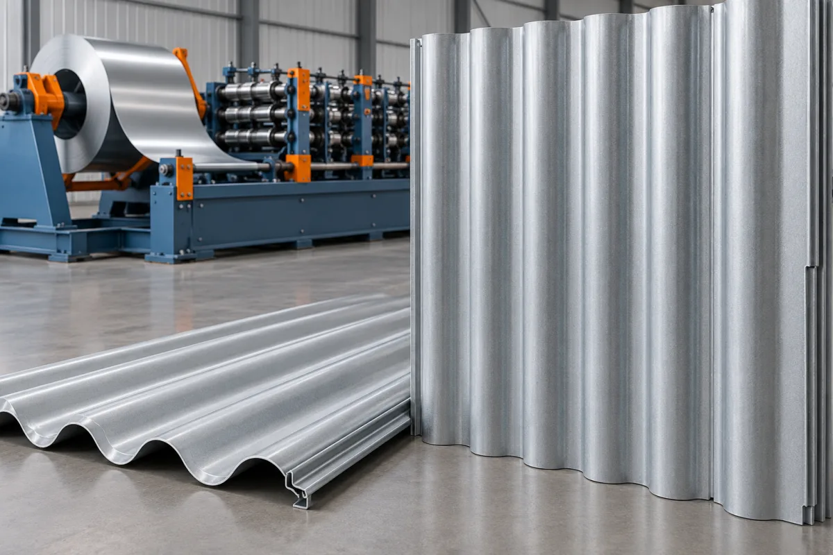
A corrugated wall cladding roll forming machine produces metal sheets with a repeating rounded wave for facade and lining applications. The curve gives the wall its visual rhythm, while the terminal waves and overlap determine how adjacent sheets form a continuous surface. Both appearance and assembly need to be defined before tooling is selected.
This route differs from angular box-profile cladding and from narrow interlocking siding. It makes a corrugated sheet, not a complete wall system. Corners, openings, support arrangements and any concealed layers remain separate parts of the finished facade design.
Which corrugation should the product range use?
Specify wave pitch, depth and contour rather than choosing only a commercial nickname. A shallow close-pitched wave creates a different appearance from a deeper, more widely spaced section. The terminal-edge positions must also suit the intended overlap.
Where the business is matching an existing product, measure an undamaged reference and assemble it with new trial sheets. Similar depth alone does not establish compatibility because pitch or wave contour may differ.
How does wall orientation affect the brief?
Vertical and horizontal layouts create different relationships with openings, corners and joints. Identify the intended orientation so the product package can show the relevant edge and termination details. Do not assume a drawing for one installation arrangement automatically covers the other.
The roll former produces the same longitudinal waves regardless of where the sheet is later installed. Orientation becomes a manufacturing issue when it changes cut lengths, end preparation, fixing features or the way orders are labeled and packed.
What belongs in the corrugated-wall drawing?
- Wave pitch, depth and approved curve.
- Overall width and assembled effective cover.
- Both terminal waves and overlap direction.
- Visible-face coating and material specification.
- Required lengths and end preparation.
- Closure, corner and opening interface references.
Use consistent measurement datums. A corrugated section is not fully described by measuring one crest and one valley at convenient points. Record enough of the repeating contour to establish that trial panels match the intended product.
How is the rounded sheet manufactured?
The coil is supported and guided into progressive roll stages that develop the waves across the strip. The finished contour and terminal edges are then presented to the chosen cutting arrangement. Supported takeoff moves the sheets to inspection and stacking.
Review contact through the entire route. A rounded crest can be marked or dented by an unsuitable support after forming. Comparing a panel at the machine exit with the same panel after packaging helps identify where damage is introduced.
How should facade finish be specified?
State grade or alloy, base-metal thickness, coating and visible-face orientation. Architectural orders may require consistent appearance across adjacent panels, so material-batch identification and order grouping can be important operational details.
Agree the viewing conditions used for approval. Curved surfaces reflect light differently across each wave, and photographs taken at different angles can be misleading. Separate coating defects, scratches and permanent dents from normal changes in reflection.
Can perforated or curved cladding be included?
Perforation is an additional process requirement. Define hole pattern, open area, unperforated margins and the relationship between holes and formed waves. The sequence must be reviewed with the actual material and contour rather than assuming any perforated strip can be run through the same tools.
Longitudinal curvature also needs its own scope. A straight-sheet former does not automatically produce a controlled architectural radius. Identify the separate equipment or approved assembly method responsible for the curved application and include that interface in trials.
What changes for mixed facade orders?
Openings and facade zones can create many lengths within one order. The line needs an appropriate cut-list method, but finished pieces also need clear identification and separation. Discuss package order and handling with the people who will assemble the wall.
Short pieces should transfer without losing support, while long pieces need a clear discharge path. Use the real length distribution to evaluate accepted output. A demonstration of identical full-length sheets may not represent normal cladding work.
How should the wall assembly be checked?
Join multiple panels on representative supports and check effective cover, wave alignment and terminal overlap. Fit the specified closures or trim references. Inspect both the individual section and the visual continuity of the assembled surface.
- Confirm wave dimensions and contour.
- Check edges along the length and near cut ends.
- Measure assembled cover without forcing the lap.
- Inspect finish under agreed lighting.
- Verify required perforation or special features.
- Recheck condition after normal packing.
Record any adjustments needed during assembly. A panel should not be approved only because an installer can pull it into position with unexpected force or local alteration.
Frequently asked questions
Can the same corrugated sheet be used for a roof?
That depends on the approved roof system and its details. The machine's ability to form a section does not establish the required roof fastening, support or weathering arrangement.
Does changing wave depth need new tools?
Usually it requires a specific tooling review and may require replacement parts. Request the supported profile matrix rather than assuming depth is an ordinary controller adjustment.
Can holes be added without affecting forming?
Perforation changes the strip presented to the tools and must be assessed with its pattern and margins. Trial the actual perforated material and inspect the final hole condition and wave geometry.
Why retain a multi-panel sample?
It records overlap and visual continuity that a single cross-section cannot show. It is useful when later production must match an established facade appearance or existing stock.
What should a quotation include?
Include the complete corrugation drawing, material and finish matrix, order lengths, special features and handling plan. Identify perforating, curving and trim production as separate scope where required.
Specify the wave and the wall together
The best corrugated-cladding production brief connects a repeatable wave to its installed overlap and visible finish. With those references defined, the equipment trial can demonstrate a saleable facade product rather than merely a corrugated strip.

Continue your research
- Wall Cladding Roll Forming Machines
- Wall Panel Roll Forming Machine
- Metal Siding Roll Forming Machine
- Box Profile Wall Panel Roll Forming Machine
- Trapezoidal Wall Cladding Roll Forming Machine
- Vertical Metal Siding Roll Forming Machine
- How Wall cladding roll forming machine Works
- How To Choose a Wall cladding roll forming machine
- Wall cladding roll forming machine Price: What Affects the Cost?
Configuration & specification inputs
Match the configuration to your section drawing, material and production requirements.
| Parameter | Requirement / confirmation needed |
|---|---|
| Profile geometry | Approved curved wave with defined pitch, depth, terminal edges and installed cover. |
| Material | Specified grade or alloy, coating and visible-face orientation with traceable material batches. |
| Thickness & grade | Base-metal thickness paired with the intended wave and optional perforation pattern. |
| Process route | Coil guidance, progressive corrugation, specified features, cutting and protected takeoff. |
| Cutting | Mixed facade lengths with controlled end-wave condition and order identification. |
| Output | Accepted cladding packages for the stated length mix and finish inspection. |
| Electrical supply | Utilities for corrugating, feature-making and handling equipment in the agreed scope. |
| Acceptance | Wave contour, multi-panel overlap, trim fit, optional features and finish after packing. |