
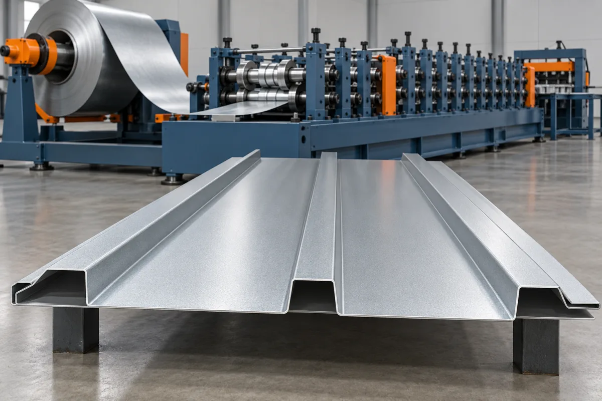
A box profile wall panel roll forming machine produces cladding with a repeating angular rib pattern and clearly defined flats. The finished wall appearance depends on the proportions of the crests, valleys and visible rib walls, while installation depends on the terminal laps and fixing arrangement. Those two sets of requirements belong in the same product drawing.
Box profile is a descriptive market term, not one universal cross-section. It can overlap with the term trapezoidal, and locally supplied products may differ significantly. The equipment should therefore be selected for an approved section rather than for the name alone.
How should the box profile be defined?
Show the crest width, valley width, rib depth and rib-wall angle. Identify any smaller stiffening features and both terminal edges. A front elevation can communicate the visual rhythm, but the cross-section explains how the sheet is actually formed and assembled.
Include an assembled pair to establish effective cover. Overall sheet width is not the same as installed contribution because part of the edge is consumed by the overlap. Keep both measurements visible in the drawing and order documentation.
What makes the wall application different from roofing?
Wall orders can emphasize visible alignment, corners, openings and changes in facade direction. A roof-profile photograph does not explain those interfaces. Identify the intended vertical or horizontal orientation and the trims that complete the wall system.
The machine can reproduce a section, but it does not decide whether that section is suitable for every wall arrangement. Manufacturing requirements should follow the selected cladding system, including fastening and support details where they affect the product.
Which panel interfaces deserve early attention?
- The side lap between neighboring sheets.
- The relation between rib pitch and opening trims.
- Corner and base details that contact the sheet.
- Required end cuts, notches or other local features.
- Any closure that follows the box-shaped contour.
Use representative accessories during the product review. A section can measure correctly in isolation but still leave an unsuitable interface if a trim was designed for another rib pattern or a different lap direction.
How does the forming route create the panel?
Coil payoff and entry guides establish the strip path. Successive stages develop the angular ribs and terminal edges until the drawing is reproduced. Length control and cutting then produce the ordered sheets, followed by inspection, takeoff and packaging.
Discuss the planned forming sequence and the location of optional operations. Film application or marking may be needed for appearance-sensitive orders. Holes and notches, where specified, need a defined production method rather than being assumed to appear automatically in a basic former.
How should broad flats and coating be assessed?
Agree the visible face, material grade, base-metal thickness and coating system. The broad flats can make surface condition and reflected-light appearance prominent. Inspection should use agreed support and lighting so a sample is not approved under one condition and rejected under an unrelated one.
Check bends for coating damage and flats for contact marks, then repeat the assessment after normal handling. Distinguish permanent shape deviation from temporary deflection caused by unsupported inspection. Retain representative approved samples with the material identification.
Can rib spacing or height be changed on one line?
Changing the rib pattern may require different rolls, guides and cutoff parts. A variable-width capability does not automatically provide variable rib geometry. Ask for a product matrix explaining which dimensions are adjustable and which require tool changes.
For multiple profiles, include first-good-panel recovery in the changeover demonstration. The operator needs to recover the correct lap, cover and appearance, not simply move the stands to another position. The cost of inspection and startup scrap belongs in the comparison.
What handling arrangement suits wall orders?
Wall schedules often combine many lengths around openings and facade zones. Define how cut pieces will be identified, separated and packed in the installation sequence. A machine can make the correct lengths while poor sorting still creates substantial site work.
Support long pieces throughout transfer and prevent local pressure on angular crests during stacking. Review package restraints using actual panels. Finish protection should not rely on a theoretical stack arrangement that has never been demonstrated with the chosen section.
How should acceptance connect geometry to appearance?
- Confirm the drawing, material and exposed-face orientation.
- Measure ribs, terminal edges and finished lengths.
- Assemble sheets to verify cover and lap continuity.
- Fit relevant corners, closures and opening references.
- Inspect the visible face under agreed conditions.
- Repeat key checks after normal takeoff and stacking.
- Record accepted output for a realistic wall order.
A multi-panel mock-up is particularly useful for a wall product because small recurring differences can become visible across a facade. Keep that assembly as a reference alongside individual dimensional records.
Frequently asked questions
Is box profile the same as trapezoidal?
The terms can overlap in commercial use, but they do not define an identical drawing. Compare the actual rib dimensions and terminal details before deciding that tooling or accessories are shared.
Can roof panels be sold as box wall cladding?
Only where the specified wall system uses that section. Review orientation, supports, fixings and trims. A manufacturing similarity does not establish suitability for every facade detail.
Will the machine also make corner trims?
Not automatically. Corner and opening trims may need folding or separate roll tools. Include them in the overall equipment plan even if they are outside the main panel line.
Can a wide flat be accepted from photographs?
Photographs help record observations but do not replace an agreed physical inspection. Lighting, support and viewing direction can change the apparent surface condition significantly.
How should production output be measured?
Use accepted wall orders after cutting, inspection and packing. State the length mix, finish requirements and included delays so the result reflects the panels that can actually be delivered.
Start with the facade section and its interfaces
A complete box-profile brief connects the visible rib pattern to the lap, accessories and finish standard. That makes the machinery comparison practical and keeps the finished wall product, rather than a generic ribbed sheet, at the center of the purchase.

Continue your research
- Wall Cladding Roll Forming Machines
- Wall Panel Roll Forming Machine
- Metal Siding Roll Forming Machine
- Corrugated Wall Cladding Roll Forming Machine
- Trapezoidal Wall Cladding Roll Forming Machine
- Vertical Metal Siding Roll Forming Machine
- How Wall cladding roll forming machine Works
- How To Choose a Wall cladding roll forming machine
- Wall cladding roll forming machine Price: What Affects the Cost?
Configuration & specification inputs
Match the configuration to your section drawing, material and production requirements.
| Parameter | Requirement / confirmation needed |
|---|---|
| Profile geometry | Box-shaped crest, valley and rib-wall geometry with separately drawn terminal laps. |
| Material | Specified coated metal with identified exposed face and architectural finish criteria. |
| Thickness & grade | Material grade and base-metal thickness combinations approved for the complete box section. |
| Process route | Guided coil entry, angular-rib forming, lap completion, cutting and facade-order stacking. |
| Cutting | Finished lengths and usable terminal ribs with any special ends explicitly scoped. |
| Output | Accepted wall orders after appearance checks, sorting and packaging. |
| Electrical supply | Site supply and auxiliaries for forming, cutoff and selected handling equipment. |
| Acceptance | Relaxed section, assembled cover, corner and closure interfaces, visible finish and package condition. |