
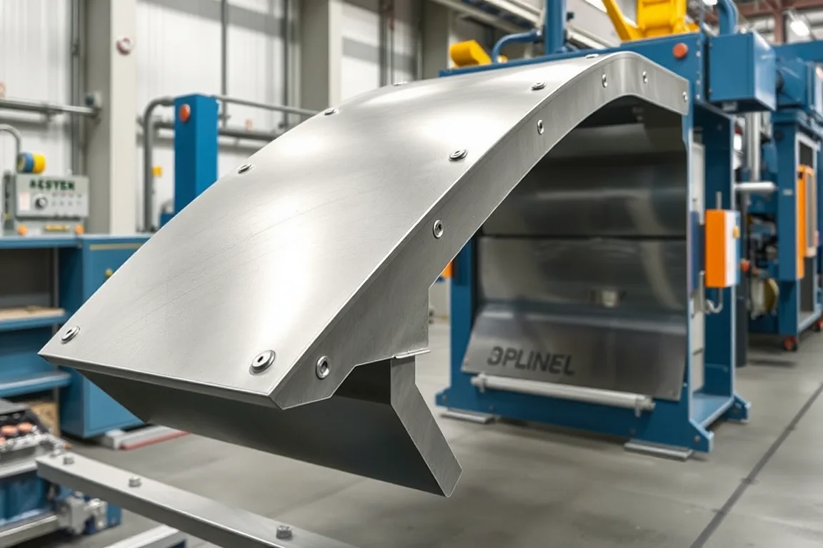
A heavy truck side member is a primary longitudinal chassis structure, and the machine that forms it must be assessed against a controlled part drawing and a validation plan. Roll forming can produce long, consistent sections with integrated holes and local features, but it only suits a side member whose cross-section stays largely constant along the length. When the drawing shows deep height changes, large cutouts, or flanges that vary substantially from end to end, the production route may need to combine roll forming with pressing, coping, or fabrication rather than forcing all geometry through a single set of rolls. This article explains the exact application, the interfaces a roll forming machine must respect, and how to separate forming from assembly, certification and in-service performance.
What the side member does in the chassis frame
A side member, sometimes called a frame rail or chassis rail, runs along each side of the truck and carries bending and torsional loads between the axles and the body mounting points. It interfaces directly with crossmembers, brackets for suspension and powertrain, and sometimes a reinforcement or inner rail. Those interfaces are not incidental: hole positions, flange angles and datum surfaces determine whether later assembly and alignment work. A roll forming machine is therefore not judged by output alone but by whether it holds the drawing-defined section and feature placement across the full part.
Why constant-section geometry decides the route
Roll forming develops a strip progressively through consecutive pass stations, each adding a controlled bend until the intended section is reached. This works well when the section is essentially constant. A side member often has a constant central zone but may need height transitions, local embossments, or a taper toward the ends. Those varying features can sometimes be produced by secondary operations after forming, such as punching, notching, or local pressing. If too much variation is imposed, each roll pass must accommodate the worst condition, and the machine may become impractical or the tooling too complex. The honest evaluation is geometry-led: first confirm how much of the rail is genuinely constant, then decide whether roll forming should produce the base section and secondary operations complete the part.
Reading the drawing: datums, holes, flanges and interfaces
The part drawing defines the datum scheme that inspection will use, and that scheme should be agreed before tooling design. Hole patterns for brackets and crossmembers need position and diameter tolerances, often with edge-distance requirements. Joining flanges are the surfaces where the side member meets crossmembers or reinforcements, so their angle and flatness matter. Assembly interfaces may include a mating inner rail or a bracket that must sit flush. A roll forming machine can incorporate piercing stations and a cutoff, but each additional operation adds complexity in tool access and scrap removal. The drawing also indicates whether the part is left-hand, right-hand, or symmetrical, which affects tooling layout and changeover strategy.
Material and thickness inputs that drive tooling
The buyer specifies the base-metal grade and thickness range; those inputs are not machine ratings. Automotive steels can vary from mild forming grades to high-strength grades, and higher strength generally changes bend radii, springback behaviour, and the amount of forming force required. Springback compensation is built into pass design, but it must be validated with the actual material. Coating type and surface condition also matter, because they affect friction and the risk of marking. If the drawing permits more than one grade or thickness, the machine and tooling must be assessed for the full range, not just the easiest condition. Any operating range claimed by a supplier requires verification with the buyer's actual coil.
The production route and where roll forming stops
A traceable route begins with coil feed, moves through precision forming, then feature and cut operations, then joining where the part requires it, and finally dimensional verification. For a side member, joining may include attaching reinforcements or brackets, which is assembly rather than forming. Roll forming normally delivers a formed rail in the flat or final section with holes and cut ends; it does not by itself produce a completed chassis assembly. Keeping that boundary clear prevents the mistake of expecting a forming machine to deliver what is actually an assembly-line responsibility. Downstream operations such as welding, bolting or adhesive bonding have their own process controls and inspection.
Cutoff, piercing and feature integration
Confirm whether cutoff is profile-supported, what cut lengths are required, and what end quality is acceptable. A flying cutoff or a stationary cut after forming can be used depending on line design, but the choice affects cycle time and end squareness. Piercing stations can create holes and slots in the formed section, but the drawing must allow access for punches and dies. Local forming, such as a small embossment or a flange jog, may need a dedicated station. The machine scope should list every feature operation and identify which are performed in-line versus off-line. That list becomes the basis for cycle-time and scrap calculations.
Assembly, certification and in-service performance boundaries
Roll forming is a production method. It does not demonstrate compliance with an OEM's structural, durability or crash requirements. Those are established by the truck manufacturer's engineering and qualification process using validated materials, joint designs, and test programs. The machine builder's responsibility is typically limited to forming the part to the agreed drawing and inspection criteria. Statements about vehicle performance should be separated from equipment scope. A general roll-forming capability is not evidence of a specific part's fitness. This distinction matters when comparing quotations and when planning validation activities.
Inspection and acceptance planning
Inspection datums should match the chassis drawing, and measurement methods should be agreed before tooling approval. First-off parts confirm setup; a representative steady-production sample confirms that the process holds over time. Gauges and fixtures used for acceptance should be identified in the quality plan. Key checks often include section dimensions, hole position, flange angle, length, and end condition. Where joining is part of the finished part, the joined assembly should also be measured against the drawing. The acceptance criteria are drawing-driven, not machine-driven, so the machine is judged by the parts it produces with the actual material.
Comparing roll forming with pressing and fabrication
Pressing can produce parts with significant height variation or complex local features that roll forming cannot handle in a single pass, but press tooling is generally part-specific and less suited to very long, constant sections. Fabrication, such as cutting and welding plates or channels, offers flexibility for low volumes or unusual geometry but usually involves more labour and more dimensional variation. Roll forming tends to be effective for long, constant or near-constant sections with integrated holes and cut lengths, and it can be economical at volume. A hybrid route, where roll forming produces the base section and pressing or machining adds local features, is often the practical answer for side members with mixed geometry. The right choice depends on the drawing, annual volume, and the acceptable level of secondary operations.
Practical checklist before committing to a line
- Confirm the section is constant over the majority of the rail length, and list every varying feature separately.
- Agree datums, measurement method and acceptance criteria before tooling approval.
- Specify material grade, thickness range, coating and allowable variation, and require validation with that material.
- List all in-line operations: forming, piercing, local forming, cutoff and any joining.
- Define cut lengths, end quality and any secondary operations needed to complete the part.
- Separate production hardware from part-validation and certification responsibilities.
- Plan changeover steps, setup scrap and unloading time where relevant.
- Inspect first-off pieces and a steady-production sample with the agreed gauges.
- Compare the written equipment scope with all operations needed for a finished part.
- Define accepted output per shift using the actual profile and material, not a demonstration substitute.
FAQ: heavy truck side member roll forming
Can roll forming produce a side member with a tapered or stepped height?
A constant-section roll forming line is built for a stable profile, so a taper or step is usually produced by secondary operations such as pressing, notching or machining after the base section is formed. If the height change is gradual and limited, it may be feasible to design passes that accommodate it, but that requires specific engineering evaluation with the actual drawing. The safe assumption is that roll forming handles the constant portion and other processes handle the variation.
How should material grade affect tooling and pass design?
Higher-strength steels generally need larger bend radii, more springback compensation and greater forming force, and they may be more sensitive to edge cracking. Pass design must be validated with the specified grade and thickness range. If the drawing allows multiple grades, the tooling should be assessed for the full range, and the buyer should provide the material for trials. A machine should not be accepted on the basis of a different, easier material.
What does profile-supported cutoff mean for a side member?
Profile-supported cutoff means the cutting operation is designed to work with the formed section so that the cut end remains within tolerance and the section does not collapse or distort. For a heavy side member, cut length, end squareness and burr condition should be defined on the drawing. The cutoff method also affects cycle time and whether the line can run continuously. The machine scope should state how cutoff is performed and what end quality is expected.
Can piercing and joining be integrated into the roll forming line?
Piercing is commonly integrated as in-line stations, provided the drawing allows punch and die access. Joining is less often fully integrated because it may involve welding, bolting or adhesive processes with separate controls. Some lines include joining stations or transfer to an assembly cell. The key is to define which operations are in-line and which are off-line, and to ensure the equipment scope matches the finished-part requirements. Integrated operations can reduce handling but add tooling and maintenance complexity.
How is acceptance handled when the part is later assembled into a chassis?
Acceptance of the formed part is based on the part drawing, using agreed datums and gauges. Chassis-level performance is validated by the truck manufacturer through its own engineering and qualification processes. The machine builder should provide parts that meet the drawing and inspection plan; it does not certify the vehicle. Keeping these responsibilities separate helps avoid confusion during procurement and validation.
What should be compared when evaluating alternative production routes?
Compare tooling life and flexibility, achievable geometry, dimensional repeatability, labour content, changeover needs and scrap. Roll forming suits long constant sections and higher volumes; pressing suits complex local features; fabrication suits low volumes or unusual geometry. A hybrid route may combine them. The comparison should use the actual drawing and material, and should include all secondary operations needed to deliver a finished part.
Separating forming from validation
A heavy truck side member roll forming machine is a production tool, and its value is measured by whether it produces drawing-compliant parts with the specified material. Coil feed, forming, piercing, local forming and cutoff belong to the machine scope; joining, chassis assembly and vehicle certification belong to the manufacturer's processes. Agreeing datums, measurement methods and acceptance criteria before tooling approval keeps those boundaries clear. Validating with the actual profile and material, rather than an easier substitute, is the most reliable way to confirm that the line is suitable for the intended side member.

Continue your research
- Automotive Roll Forming Machines
- Automotive Bumper Beam Roll Forming Machine
- Automotive Door Beam Roll Forming Machine
- Automotive Seat Rail Roll Forming Machine
- Automotive Window Guide Channel Roll Forming Machine
- Trailer Side Wall Post Roll Forming Machine
- How Automotive roll forming machine Works
- How To Choose a Automotive roll forming machine
- Automotive roll forming machine Price: What Affects the Cost?
Configuration & specification inputs
Match the configuration to your section drawing, material and production requirements.
| Parameter | Requirement / confirmation needed |
|---|---|
| Profile geometry | A truck side member may have varying features along its length. Check whether a constant-section roll-forming route fits the actual geometry or whether pressing and fabrication are more appropriate. |
| Material | Drawing-specified automotive steel or other validated alloy |
| Thickness & grade | Buyer to specify base-metal thickness and grade; operating range requires supplier verification. |
| Process route | Traceable coil feed → precision forming → feature/cut operations → joining → dimensional verification |
| Cutting | Confirm profile-supported cutoff, cut lengths, end quality and any secondary operations. |
| Output | Define accepted output per shift with the actual profile and material. |
| Electrical supply | Buyer to state voltage / frequency / phase. Installed power requires a confirmed equipment schedule. |
| Acceptance | Specify piercing, local forming, cutting and any joining alongside the main forming operation. Inspection datums should match the chassis drawing. Vehicle structural performance requires the manufacturer's engineering and qualification process. |