
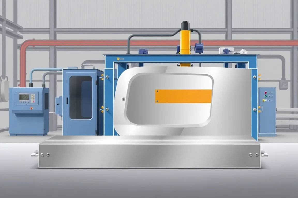
An automotive door beam roll forming machine is built around a controlled part drawing, not around a generic roll-forming platform. The machine’s purpose is to turn drawing-specified automotive steel or another validated alloy into an impact beam whose section geometry, datums, holes, joining flanges and assembly interfaces match the approved part definition. That definition also establishes relationships to the door module, latch and hinge areas, and any adjacent reinforcement, so dimensional acceptance is a separate activity from vehicle-level side-impact validation.
The equipment sits within the wider category of automotive roll forming machines, but its scope differs from neighboring products. A bumper beam line typically handles a different closed or multi-thickness section and energy-management interfaces. A body structural profile line may produce longer, more architectural members. A truck side beam line works to different handling and straightness priorities. For a door beam, the main engineering challenge is usually a relatively compact, high-strength section with several functional features created in a traceable sequence.
What the finished door beam profile must deliver
The finished profile is the starting point for every decision. Its cross-section may be open, hat-like, or otherwise shaped to provide bending resistance while fitting within the door’s internal space. Because door beams are typically made from higher-strength steel, the section’s bend radii, flat lengths and flange angles are influenced by forming limits. The drawing should identify which surfaces are functional: the outer face that may contact trim, the mounting faces that join to the door structure, and any edge that must remain free of distortion.
Holes and slots are not cosmetic. They may be used for location during assembly, for fasteners, for drainage, or for weight reduction. Their position relative to the datum scheme is what makes the part usable. A dimensional sample can confirm that a particular piece matches the drawing at the time it was measured, but it does not establish side-impact performance. That qualification belongs to the validated vehicle or assembly process, using the OEM’s approved procedures.
Joining flanges are equally important. Some beams are joined to end brackets or reinforcements by spot welding, riveting, or adhesive bonding. The roll-formed profile may need specific flange widths, angles, and surface conditions for those joining methods. If the design calls for a swept or curved beam, the profile’s final geometry includes a longitudinal curvature that must be formed without collapsing the section.
Coil feed, material and traceability requirements
The production route starts with traceable coil feed. Material is typically drawing-specified automotive steel or another validated alloy. The buyer specifies base-metal thickness and grade; any operating range requires supplier verification against the actual coil and part. Coil width, edge condition, and surface coating affect both forming behavior and downstream joining.
Traceability matters because a door beam is a safety-related part. Coil identity should be linked to the production run, and that linkage should survive cut-off, joining, and any secondary operations. The line’s control system may record coil batch, line parameters, and production counts, but the measurement method and record retention are agreed between the buyer and the equipment supplier. The goal is not an abstract data stream; it is the ability to associate a finished beam with the material and process conditions that produced it.
High-strength material can change the whole forming strategy. It may require different bend radii, more forming passes, and springback compensation. Springback is the elastic recovery of the strip after it leaves a roll station; if it is not accounted for, the final section will not match the drawing. Forming simulation or trial evidence can help show whether the proposed pass sequence can produce the required profile before the tooling is approved.
Production route from coil to verified part
The representative process route is traceable coil feed to precision forming, then feature and cut operations, joining, and dimensional verification. This route is a useful basis for reviewing scope, but the exact sequence depends on the part. In some lines, piercing and notching occur after forming and before cut-off; in others, certain holes are created in a separate press or offline cell. Joining may be integrated into the line or performed in a downstream station.
Precision forming is achieved through a series of roll stations. Each station progressively bends the strip while controlling the strip’s position. The number of stations and the distribution of bend angles are tooling decisions based on the section, material, and thickness. More stations do not automatically produce a better part; they influence how gradually the material is deformed and how much springback compensation can be distributed.
Feature and cut operations include piercing, slotting, notching, and cut-off. Cutting requirements should be confirmed for profile-supported cutoff, cut lengths, end quality, and any secondary operations. A cut-off that is supported by the profile can help maintain end squareness and reduce distortion. After cut-off, the part may need deburring, end forming, or joining. Dimensional verification follows, using the agreed datums and measurement method.
Tooling alternatives and pass development
Tooling alternatives begin with the forming concept. Conventional roll forming uses a sequence of driven rolls to bend the strip progressively. For a door beam with a complex or high-strength section, the supplier may propose additional passes, a different roll arrangement, or localized forming features. Some profiles are produced with a combination of roll forming and secondary press operations. The choice affects changeover, maintenance, and the ability to hold tolerances.
Pass development is the engineering work that determines the roll profiles. It considers the material’s forming limits, the target section after springback, and the location of holes and flanges. Simulation can reduce trial-and-error, but it does not replace physical trials with the actual material and part configuration. Tooling materials and coatings also matter for wear and surface finish, especially with coated or higher-strength steels.
Another tooling alternative is the cut-off method. A shear cut-off is common, but the tooling must support the profile to avoid crushing or twisting. If the end requires a specific shape or burr condition, a different cut-off or secondary operation may be needed. The buyer should compare the written equipment scope with all secondary operations required to produce a finished part.
Separate operations: joining, finishing and assembly
Joining is often a separate operation from roll forming. A door beam may be joined to end brackets, mounting plates, or other reinforcements. Spot welding, riveting, adhesive bonding, and other methods each impose their own requirements on flange geometry, surface condition, and access. If joining is integrated into the line, the line’s cycle time and changeover must account for it. If joining is offline, the line produces a formed and cut beam that then enters a separate cell.
Finishing operations may include deburring, coating touch-up, or application of sealant. These are not always part of the roll forming machine scope. The same applies to packaging and logistics. Separating these operations in the quotation helps the buyer see the true cost and responsibility boundaries.
Certification and in-service performance are also separate. A machine supplier can provide equipment that produces parts to the agreed drawing and acceptance criteria, but the vehicle-level side-impact performance is validated by the OEM or Tier 1 with the complete door assembly. Do not treat a dimensional sample as evidence of crash performance.
Changeover, setup and production targets
Changeover requirements matter more than an isolated no-load speed. A door beam line may run one part for a long period, or it may need to switch between variants. The changeover steps, setup scrap, and time to first good part should be defined. If the line includes automated tooling adjustment or quick-change cassettes, the buyer should understand what is adjusted and what requires manual intervention.
Production targets should be defined as accepted output per shift with the actual profile and material. That figure depends on cycle time, joining time, inspection frequency, and scrap rate. A no-load speed does not represent real output. The buyer should also state the electrical supply: voltage, frequency, and phase. Installed power requires a confirmed equipment schedule, not an estimate.
Inspection, datums and accepted output
Inspection starts with the datum scheme. The drawing defines which surfaces and features establish the part coordinate system. The measurement method must be agreed before tooling approval. This includes the gauges, fixtures, and sampling plan. First-off pieces and a representative steady-production sample should be inspected with the agreed gauges. The sample should include parts from representative operating conditions, including any agreed setup or changeover cases.
Acceptance criteria cover dimensional requirements, hole positions, flange angles, cut length, and end quality. Visual criteria may cover surface defects, burrs, and marks. The buyer and supplier should agree on how to handle nonconforming parts and how to record traceability. Keep dimensional acceptance and safety-performance validation as separate documented activities.
Output should be defined as accepted parts per shift, not as machine speed. Scrap and changeover requirements affect that number. The written equipment scope should be compared with all secondary operations needed for a finished part, so that the quotation reflects the complete production route.
Practical selection checklist
- Confirm the finished profile: section geometry, datums, holes, joining flanges, and assembly interfaces.
- Specify material grade, thickness, coating, and allowable variation; require verification against the actual coil.
- Review forming simulation or trial evidence for the proposed pass sequence and springback compensation.
- Define cutting requirements: profile-supported cutoff, cut lengths, end quality, and secondary operations.
- Decide whether piercing, joining, and other features are integrated or separate.
- State changeover steps, setup scrap, and target accepted output per shift with the actual profile and material.
- Provide electrical supply details: voltage, frequency, and phase.
- Agree datums, measurement method, sampling, and acceptance criteria before tooling approval.
- Separate production hardware from part-validation responsibilities.
- Compare the written equipment scope with all secondary operations needed for a finished part.
Comparison of line configuration alternatives
One alternative is a dedicated line with fixed tooling for a single door beam variant. This can simplify operation and maintenance, but it offers limited flexibility if the part changes. Another alternative is a line with quick-change tooling or adjustable stations, which can accommodate multiple variants but adds complexity and changeover time. The trade-off is between simplicity and flexibility.
A second comparison is integrated versus separate feature operations. Integrating piercing and joining into the roll forming line can reduce handling and work-in-progress, but it increases the line’s complexity and may reduce accessibility for maintenance. Separate operations can be easier to control and change, but they add logistics and potential dimensional variation. The choice depends on part volume, variant count, and the buyer’s manufacturing strategy.
A third comparison is cut-off method. A shear cut-off that supports the profile can produce a clean end, but tooling must be matched to the section. A saw cut or secondary machining may be needed for certain end conditions, but it adds cycle time and may require additional handling. The buyer should confirm the required end quality and whether the cut-off can achieve it without damaging the profile.
Frequently asked questions
What does an automotive door beam roll forming machine actually make?
It produces the roll-formed impact beam that fits inside a vehicle door. The machine forms the section from coil, creates holes and cut features, and cuts the beam to length. Depending on the line, it may also perform joining operations. The finished beam is a structural part that transfers load during a side impact, but its side-impact performance is validated at the vehicle or assembly level, not by the machine alone.
How do I define the profile and material for a new door beam?
Start with the controlled part drawing. It should specify section geometry, datums, hole positions, joining flanges, and assembly interfaces. Material is typically drawing-specified automotive steel or another validated alloy; the buyer specifies base-metal thickness and grade. Any operating range requires supplier verification against the actual coil and part. High-strength material may require different bend radii and springback compensation.
What tooling alternatives should I compare?
Compare the forming concept, number of passes, and whether the line uses conventional roll forming or a combination with secondary press operations. Also compare cut-off methods and whether piercing and joining are integrated or separate. The tooling should be developed for the actual material and part configuration, not for a demonstration substitute. Physical trials with the agreed material are important because simulation does not replace them.
How should changeover and production targets be specified?
Specify changeover steps, setup scrap, and time to first good part. Production targets should be defined as accepted output per shift with the actual profile and material, not as a no-load speed. The target should account for inspection frequency, joining time, and expected scrap. The buyer should also state the electrical supply details so the equipment schedule can be confirmed.
What inspection and acceptance activities are needed?
Agree datums, measurement method, sampling, and acceptance criteria before tooling approval. Inspect first-off pieces and a representative steady-production sample with the agreed gauges. Include parts from representative operating conditions and any agreed setup or changeover cases. Keep dimensional acceptance separate from vehicle-level safety-performance validation.
How do I know if the line scope covers a finished part?
Compare the written equipment scope with every secondary operation needed for a finished part. That may include deburring, joining, coating touch-up, and packaging. If those operations are not in the line scope, they must be accounted for elsewhere. The quotation should distinguish production hardware from part-validation responsibilities.

Continue your research
- Automotive Roll Forming Machines
- Automotive Bumper Beam Roll Forming Machine
- Car Body Structural Profile Roll Forming Machine
- Automotive Seat Rail Roll Forming Machine
- Automotive Window Guide Channel Roll Forming Machine
- Heavy Truck Side Member Roll Forming Machine
- How Automotive roll forming machine Works
- How To Choose a Automotive roll forming machine
- Automotive roll forming machine Price: What Affects the Cost?
Configuration & specification inputs
Match the configuration to your section drawing, material and production requirements.
| Parameter | Requirement / confirmation needed |
|---|---|
| Profile geometry | A door impact beam requires the approved section, material and assembly interfaces. A dimensional sample does not establish side-impact performance; qualification belongs to the validated vehicle or assembly process. |
| Material | Drawing-specified automotive steel or other validated alloy |
| Thickness & grade | Buyer to specify base-metal thickness and grade; operating range requires supplier verification. |
| Process route | Traceable coil feed → precision forming → feature/cut operations → joining → dimensional verification |
| Cutting | Confirm profile-supported cutoff, cut lengths, end quality and any secondary operations. |
| Output | Define accepted output per shift with the actual profile and material. |
| Electrical supply | Buyer to state voltage / frequency / phase. Installed power requires a confirmed equipment schedule. |
| Acceptance | Request the measurement method, sample selection and part-traceability arrangements. Inspect parts from representative operating conditions, including the agreed setup or changeover cases. Keep dimensional acceptance and safety-performance validation as separate documented activities. |