
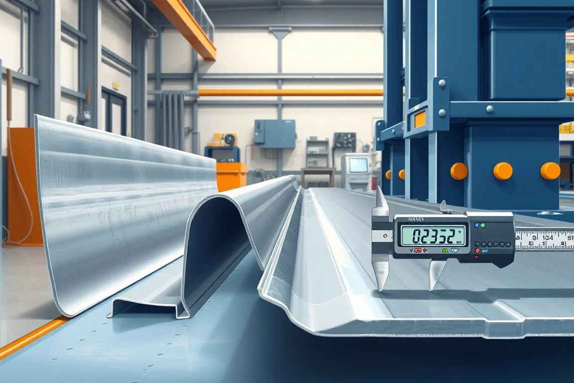
What material thickness means on an automotive roll forming line
When the keyword phrase "automotive roll forming machine material thickness" appears in a project, it usually refers to base-metal thickness: the thickness of the steel strip before forming, measured on the flat coil. That is different from the final wall thickness at a corner or flange, which changes as material flows through the passes. It is also different from a nominal gauge number, which is a trade label rather than a controlled dimension. For an automotive part, the controlling input is the specified base-metal thickness range, the grade and strength, the coating or surface condition, and the allowable variation across the coil width and along the coil length. These inputs drive roll load, pass count, springback behaviour, tooling hardness and the way the finished profile holds its datums.
A machine that forms thin, mild strip at a given width is not thereby proven on a thicker or higher-strength grade. Formability, press tonnage, drive torque and shaft deflection interact, so thickness and strength should be evaluated together rather than as independent maxima.
Why the material definition must come from the part drawing
The part drawing and its validation plan define which material is acceptable. A controlled drawing states grade, strength range, thickness with tolerances, coating, surface finish and any hole or edge requirements. Procurement of the machine then follows from those values, not the other way around. When a buyer specifies only a thickness and a profile shape, the equipment may be built around assumptions about yield strength and ductility that do not match the intended coil. That mismatch tends to appear later as springback variation, dimensional drift or edge cracking.
Automotive profiles such as bumper reinforcements, seat rails and window guides have different demands. Some are dominated by strength and crash-relevant geometry; others by sliding fit, surface appearance or hole position for fasteners. The material and thickness section of the machine specification should therefore be tied to the specific part family, not to a generic material category.
How grade, strength and coating change forming behaviour
Higher-strength steels resist bending, so they spring back more when the rolls release them. Tooling designers compensate by adjusting roll geometry, overbend and pass sequencing. That compensation is material-specific: a tool set tuned for one strength level may produce out-of-tolerance angles when the same section is run from a harder coil. Ductility also matters. Materials with limited elongation can tolerate a minimum bend radius that a more ductile grade would exceed without concern, so the radius is a material decision, not only a tooling detail.
Coating changes friction, surface finish and the risk of marking. A coated or film-protected strip may need different roll surface treatment or lubrication than bare steel. Coating thickness can also affect final dimensions where close tolerances are required. The exposed face of the part often determines which side must remain unmarked, which is a handling and roll-contact consideration separate from the base thickness.
How thickness interacts with pass design and springback
Thickness affects the bending moment required to form the section and the amount of material available at a corner. Thicker strip generally needs more forming stations or more gradual bend angles per station to avoid overstressing the outer fibre. It also increases the severity of springback because the elastic recovery is larger in absolute terms. The result is that pass count, roll diameter and drive capacity are chosen as a set for a defined thickness and strength window.
The practical consequence is that a machine's supported combinations matter more than any single maximum value. A supplier's stated maximum thickness at one width and grade does not establish capability across the range. What is useful is a written statement of which grade, strength and thickness combinations have been demonstrated together, with the tooling and pass design that supports them.
Interface between material inputs and the coiling, feeding and cutting stages
Material arrives as coil, and coil properties propagate through the line. Strip flatness, camber, thickness variation and surface condition all influence what the rolls can achieve. A traceable coil feed with controlled tension and alignment supports repeatability; inconsistent feed tension contributes to length variation and twist. The cut-off operation then depends on the profile being supported while the blade or shear acts. Cutting a thin, open section and cutting a thick, closed section are different tasks, so cut length, end quality and secondary operations must be evaluated with the actual profile and material.
Downstream joining, whether fastening, welding or adhesive bonding, is also material-sensitive. Joining parameters suited to a coated or high-strength strip may differ from those for bare mild steel, and the assembly interfaces defined on the drawing should govern how the formed part is presented to that operation.
How to specify material and thickness in a buying enquiry
A clear enquiry separates base-metal thickness and grade from coating and protective film. It states the nominal thickness, the permitted variation and the strength range, and it notes the coil supplier and whether representative samples can be supplied. It lists the profile geometry, datums, holes and joining flanges. It distinguishes the forming task from assembly, certification and in-service performance, because a machine that produces a dimensionally correct section is not thereby validated for vehicle-level requirements.
The enquiry should also state the expected accepted output per shift in terms of the actual profile and material, understanding that no verified model rating exists until the combination is tested. Voltage, frequency and phase should be stated by the buyer, and installed power should be confirmed against an equipment schedule rather than assumed.
Trade-offs when a machine must cover more than one material
A line intended to run several grades or thicknesses trades specialisation for flexibility. Wider material coverage can require more forming stations, more capable drives and a broader tooling set, and it may need changeover procedures between material families. A narrower specification may form its target material more efficiently but cannot absorb a future grade change without new tooling or a different pass strategy.
The alternatives are not simply large versus small. One approach is a line dedicated to a single high-volume part, optimised around one material combination. Another is a line with quick-change tooling for a family of similar sections. A third is a modular line where forming, piercing and cutting are configured for a defined range. Each choice shifts risk: greater flexibility can add setup and verification effort, while tighter focus can limit later part changes. The right balance follows from the product plan, not from a generic preference.
Acceptance testing with the intended material
Before tooling approval, the buyer and supplier should agree datums, measurement methods and acceptance criteria. Validation should use the actual material and part configuration, not a substitute strip. Where forming simulation or trial evidence exists, it can inform the review of pass development and springback compensation, but it does not replace dimensional verification of produced parts. Where piercing, welding or sweeping is integrated, access to critical features should be confirmed as part of the same exercise.
Acceptance should also distinguish the forming process from downstream joining and from any vehicle-level requirement. A crash-relevant component is not validated because the section matches a drawing; that performance needs separate engineering and testing.
Practical checklist for material and thickness decisions
- State grade and strength range separately from nominal base-metal thickness and its permitted variation.
- Record coating or protective film, surface finish and which face must remain exposed and unmarked.
- Provide representative samples from the intended coil supplier for trials.
- Confirm that bend radii and pass design are consistent with the specified material's ductility.
- Ask for written supported combinations of grade, strength, thickness and width, rather than unrelated maximum values.
- Agree datums, measurement method and acceptance criteria before tooling approval.
- Define accepted output per shift using the actual profile and material, and treat that figure as demonstrated only after testing.
- Separate forming capability from assembly, certification and in-service performance requirements.
Common mistakes in thickness specification
Substituting an ambiguous gauge number for a measured thickness and standard is a frequent error. Another is treating a maximum thickness at a single low-strength grade as evidence for a higher-strength grade. A third is ignoring thickness variation across the coil, which can defeat tight angle tolerances even when the nominal value is correct. Equally common is omitting the exposed face requirement, so tooling and handling decisions are made without knowing which surface must remain defect-free.
These mistakes usually surface late, when the tooling is already committed. Making the material definition explicit at enquiry stage reduces the need for rework and clarifies where responsibility lies for the formed result.
FAQ: automotive roll forming machine material thickness
Does material thickness alone determine whether a machine can form a part?
No. Thickness is one input among several. Grade, yield strength, ductility, coating, section geometry and the required tolerances together determine roll load, pass design and springback compensation. A machine specified around one thickness but a different strength may not reproduce the required angles. Capability should therefore be expressed as supported combinations rather than a single thickness figure.
How is a thickness range different from a nominal thickness?
A nominal thickness is the target value on the drawing. A range expresses the permitted variation around it. The forming process must hold dimensions across that range, not only at nominal. If the coil supplier's actual variation is wider than the drawing tolerance, the line may require adjustment or the coil may be non-conforming. Agreeing the range up front clarifies whether the machine or the incoming material is the limiting factor.
Can one roll forming line run both mild and high-strength automotive steel?
It may be possible if the tooling and pass design are developed for the harder material and the line can tolerate the associated loads. Running a high-strength grade on tooling optimised for mild steel often produces excessive springback and angle deviation. A line intended for both should be specified with the demanding grade in mind, and changeover between material families should be planned and verified rather than assumed.
Why do suppliers ask about coating and exposed face?
Coating affects friction, marking and sometimes final dimensions. The exposed face determines which roll surfaces must avoid scuffing and how the strip should be handled. These factors influence roll material, surface treatment and lubrication choices. A supplier asking about them is trying to match handling and tooling to the part's cosmetic and functional requirements, not adding unnecessary detail.
What evidence should support a claimed thickness capability?
Useful evidence ties a grade, strength and thickness to the specific section geometry, with dimensional results from produced parts. Forming simulation or trial reports can support the review, but final acceptance should rest on measurement against agreed datums and criteria using the intended material. A bare maximum thickness figure without the associated grade and section is weak evidence.
How should accepted output be described before testing?
Accepted output should be defined against the actual profile and material, with the understanding that no verified rating exists until the combination is run. The buyer and supplier can agree a target expressed as good parts per shift or per unit time, but that target becomes a demonstrated figure only after validation. Treating it as a specification before test risks disputes over what the line can achieve.
Continue your research
- Automotive Roll Forming Machines
- Automotive Bumper Beam Roll Forming Machine
- Automotive Door Beam Roll Forming Machine
- Automotive Seat Rail Roll Forming Machine
- Automotive Window Guide Channel Roll Forming Machine
- Heavy Truck Side Member Roll Forming Machine
- How Automotive roll forming machine Works
- How To Choose a Automotive roll forming machine
- Automotive roll forming machine Price: What Affects the Cost?