
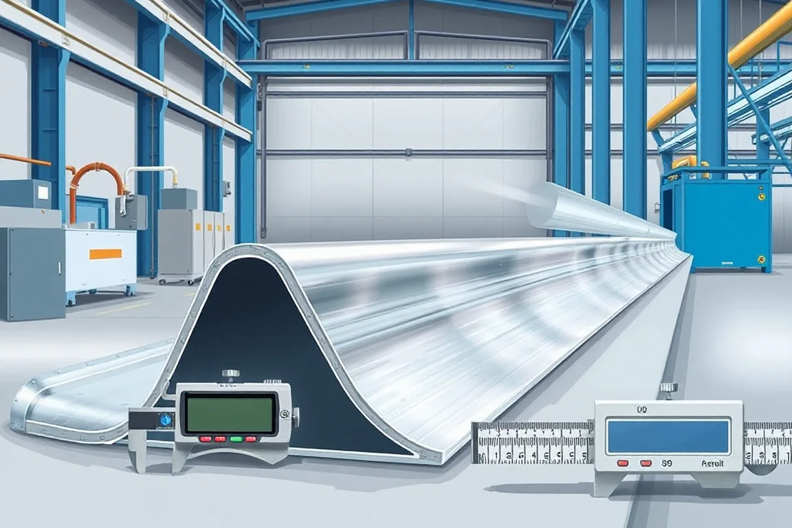
The question of material thickness for a guardrail roll forming machine is answered at the level of the purchase specification, not the machine alone. The buyer specifies the steel grade, the nominal base-metal thickness, the permitted thickness variation and the coating or protective film. The equipment supplier then confirms whether the line can form that combination into the required beam geometry. A thickness value on its own is not a machine capability; it is one variable in a set that must be supported together.
Why thickness belongs in the purchase specification
Thickness affects nearly every stage of a guardrail line. It changes the force needed at each forming pass, the springback after bending, the punch tonnage required for splice holes, the shear load at cutoff, and the way the finished beam holds its wave geometry. When thickness is treated as an afterthought, the consequences show up as wave distortion, poor lap fit, damaged edges or inconsistent hole position. The purchase specification should state the thickness as a nominal value with a tolerance band, not as an ambiguous gauge number. Gauge systems differ between materials and suppliers, so a gauge callout can leave both parties assuming different values.
The grade matters alongside thickness. A higher-strength steel at the same nominal thickness will resist forming differently than a lower-strength grade. The line that processes one grade at one thickness has not thereby demonstrated capability across a range of harder or softer materials. For that reason, the specification should define the actual grade or strength range and keep coating separate from base-metal thickness, because coating adds to the overall dimension while the forming and punching behavior is governed mainly by the base metal.
How the forming sequence interacts with material thickness
A typical guardrail forming sequence runs from coil through leveling, then punching of splice holes or slots, then progressive forming of the beam waves, then cutoff, followed by coating or assembly operations as specified. Each stage has an interface with the next. Leveling sets the flatness and internal stress state that the first forming passes receive. Punching, if performed before forming, creates holes in the flat strip; if performed after forming, the tooling must reference the formed geometry and the splice datums. Forming establishes the wave profile and the lap orientation. Cutoff must produce a clean end without collapsing the profile.
Thickness changes the balance between these stages. A heavier base metal requires more work per pass, which can affect the number of forming stations, the roll diameter, the shaft stiffness and the drive capacity. It also affects the position of the neutral axis during bending and therefore the final wave dimensions after springback. The punch tooling must be sized for the thickness range because the hole diameter and slot length should remain within the drawing limits even as the material thickness varies. If coating is applied after forming, the punched and cut edges are exposed until coated; if coating is applied before forming, the forming operation must not damage the coating beyond the agreed acceptance limits.
Coating sequence and edge treatment
Whether forming occurs before or after protective coating is a fundamental decision. Forming before coating allows the forming rolls to work bare steel, which can simplify lubrication and tooling wear, but then the punched holes and cut ends require a coating process that covers the formed shape and the exposed edges. Forming after coating preserves the coating on the flat surfaces but risks coating damage at the bends, at the punch edges and at the cutoff. The purchase specification should state which sequence applies and how edges are treated, because the acceptance criteria for coating adhesion and edge coverage differ between the two routes.
Thickness influences this decision as well. A thicker base metal may require larger bend radii, which can make some coating systems more prone to cracking at the outside of the bend. That is not a reason to avoid a sequence; it is a reason to agree the coating type, the bend radius and the acceptance method in writing before the line is built.
Comparing alternatives: single-material and mixed-material lines
One practical comparison is between a line dedicated to one grade and thickness combination and a line intended to handle a range. A dedicated line can be optimized for that combination: roll profiles, punch clearances, cutoff tooling and drive settings can be matched to a narrow envelope. A range-capable line must compromise somewhere, often in roll geometry or in changeover time between combinations. Neither is inherently superior; the choice depends on whether the plant expects to produce one barrier component repeatedly or to switch between several approved drawings.
A second comparison is between forming before coating and forming after coating, as outlined above. A third is between punching on the forming line and punching as a separate operation. In-line punching integrates the hole pattern with the forming position, which can help hole-to-wave alignment, but it also ties the punch tooling to the line speed and the thickness range. Separate punching can be more flexible for different hole patterns but adds handling and a second setup. The decision should follow from the approved drawing and the expected production mix, not from a general preference.
What a quote should define for thickness and material
A useful quote does not simply state a maximum thickness. It lists supported combinations of grade, nominal base-metal thickness and coating. It states the thickness tolerance band that the line can accept without adjustment outside normal operation. It identifies which operations occur before and after coating. It describes the punch tooling reference to splice datums and the cutoff method that supports the profile at the cut. It defines accepted output in terms of the actual profile and material, such as beams per shift that meet the drawing, rather than a standalone speed figure. It separates the cost of the forming line from the cost of coating, assembly and any secondary operations.
Installed power depends on the equipment schedule, not on a single motor rating. The buyer should state the available voltage, frequency and phase, and the supplier should confirm the power requirement for the complete line. Any performance or capacity claim should be traceable to the specific combination being quoted.
Assessing acceptance: component quality versus system approval
Acceptance of formed components should cover wave geometry, splice-hole position, lap fit and beam length. These are dimensional checks against the approved drawing and the procurement specification. They are separate from crash-testing and installation approval. Roll forming produces one or more components; it does not establish crashworthiness of a barrier system. The system behavior depends on beams, posts, spacers and connections working together, often under a tested configuration. Keeping component acceptance separate from system approval prevents the mistake of assuming that a well-formed beam is a qualified barrier.
Thickness variation within the permitted band should still produce components that meet the dimensional acceptance criteria. If it does not, the supported envelope in the specification is either wrong or incomplete. That is a subject for review with the equipment supplier, not for adjustment of moving machinery by the reader.
Practical checklist for specifying material and thickness
- State the steel grade or strength range and the nominal base-metal thickness with a tolerance band.
- Do not substitute a gauge number for a thickness and a standard.
- Specify the coating or protective film separately from base-metal thickness.
- State whether forming occurs before or after coating and how punched and cut edges are treated.
- Provide representative coil samples or clearly identify the intended coil supplier.
- Identify the approved barrier drawing, including end laps and fixing slots.
- Confirm the punch tooling references the splice datums.
- Define accepted output per shift using the actual profile and material.
- State the available voltage, frequency and phase, and request a complete equipment schedule.
- Keep component dimensional acceptance separate from system crash-testing and installation approval.
FAQ
Can one guardrail roll forming machine handle every material thickness?
No single machine can be assumed to handle every thickness and grade. The practical envelope is the set of combinations the supplier confirms in writing for the specific line and tooling. A maximum thickness figure alone does not describe that envelope, because grade and coating also affect forming behavior.
Why is a gauge number not enough for thickness specification?
Gauge systems are not consistent across materials and suppliers, so a gauge callout can mean different actual thicknesses to different parties. A nominal thickness with a tolerance band and a referenced standard removes that ambiguity and gives both buyer and supplier the same basis for verification.
Does coating thickness count toward the forming envelope?
The forming and punching behavior is governed mainly by the base metal. Coating adds to the overall dimension and affects surface condition and bend performance. The specification should state coating separately from base-metal thickness, and the supported combination should list both, because a coating that cracks at the bend is a different problem from a base metal that will not form.
Should punching happen before or after forming?
Both sequences are used. Punching before forming creates holes in flat strip and can simplify tooling access, but it requires that forming not distort the hole position beyond the drawing limits. Punching after forming can keep the hole referenced to the formed wave, but the tooling must accommodate the profile and the splice datums. The choice depends on the drawing and the production mix.
What does accepted output mean for a guardrail line?
Accepted output is the number of components per shift that meet the dimensional acceptance criteria for the actual profile and material being run. It is not a standalone speed rating. Quoting accepted output for a specific combination is more useful than a maximum speed that may not apply to the intended product.
Does thickness affect hole position in the finished beam?
Thickness affects springback and the neutral axis during bending, so it can influence the final position of punched features relative to the wave. That is why the punch tooling should reference the splice datums and why acceptance checks include splice-hole position and lap fit, not only wave shape.
How should a buyer compare quotes that state different thickness ranges?
Ask each supplier to state supported combinations of grade, nominal base-metal thickness, tolerance band and coating, along with the operations sequence. A quote that lists a range without combinations cannot be compared directly to one that lists combinations. The comparison should focus on whether the intended production envelope is covered.
Distinguishing thickness from nearby topics
Material and thickness is one part of the broader selection process. It is distinct from questions about how a guardrail roll forming machine works, how to choose one, what affects cost, what production speed and output are achievable, how roller and tooling design is approached, how defects are diagnosed, and what maintenance is needed. A thickness decision feeds into all of those, but it does not replace them. Keeping the topics separate helps avoid treating a machine as suitable for every barrier component, when posts, beam sections and spacer blocks may need different processes.
W-beam and two-wave beam describe the same broad geometry; thrie beam and three-wave beam overlap in the same way. The approved drawing, not the name alone, identifies genuine differences. The material and thickness specification sits on top of that drawing and should be agreed before equipment is ordered.
Continue your research
- Guardrail & Crash Barrier Roll Forming Machines
- W Beam Guardrail Roll Forming Machine
- Thrie Beam Guardrail Roll Forming Machine
- Guardrail C Post Roll Forming Machine
- Guardrail Sigma Post Roll Forming Machine
- Guardrail U Post Roll Forming Machine
- How Guardrail roll forming machine Works
- How To Choose a Guardrail roll forming machine
- Guardrail roll forming machine Price: What Affects the Cost?