
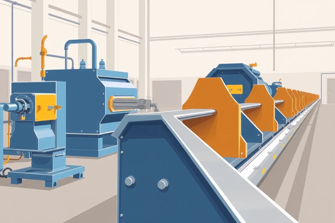
What a guardrail roll forming machine actually does
A guardrail roll forming machine transforms flat steel strip into a continuous formed beam with the wave profile, splice holes, and cut lengths required for a barrier system. The machine does not produce a complete roadside barrier. It produces one or more components—typically the beam—while posts, spacers, and connection hardware follow separate manufacturing routes. The machine's job is to take a coil of steel and deliver a dimensional, hole-patterned component that matches an approved drawing. Understanding how that happens requires following the strip from entry to exit and recognizing where each operation is physically located.
The core sequence is leveling, punching, roll forming, and cutoff. Coating and assembly operations may occur in line or off line depending on the specification. Each transition between these stages is a process boundary where the part changes state, changes reference, or changes handling method. A clear line layout identifies those boundaries and assigns responsibility for the interfaces between them.
Start from the approved barrier drawing, not the machine
The machine's tooling and control settings are derived from the barrier drawing. That drawing defines the wave geometry, the bolt-slot pattern, the lap orientation, and the post connection geometry. Before evaluating a roll forming machine, the buyer should have a controlled drawing that specifies the beam profile, the base-metal thickness and grade, the coating sequence, and the required cut lengths. Without that drawing, the machine cannot be configured meaningfully and acceptance criteria remain undefined.
W-beam and two-wave beam describe the same broad geometry. Thrie beam and three-wave beam likewise overlap. Genuine differences appear in the approved drawing: wave depth, wave spacing, beam width, and the position of splice holes relative to the wave. The drawing also dictates whether the beam is used as a single member or as part of a nested or lapped assembly. These distinctions drive tooling design more than the informal name of the profile.
Stage one: coil handling and strip leveling
The process begins with a coil of steel strip mounted on a decoiler or uncoiler. The strip is fed into a leveler, which removes coil set and cross-bow so the strip enters the forming rolls flat and consistent. Leveling matters because residual curvature in the strip can cause the formed beam to twist, camber, or vary in wave geometry along its length. A leveler with adjustable roll positions allows the operator to tune the strip condition for the incoming coil.
The interface between the leveler and the first forming station is critical. If the strip is not flat and properly aligned, every downstream station inherits that error. The line layout should show how the strip is guided and tensioned between the decoiler, leveler, and first roll stand. The buyer should confirm who supplies the coil-handling equipment and how it integrates with the roll forming machine's controls.
Stage two: punching and slotting
Punching creates the bolt slots, splice holes, and any other openings required by the barrier drawing. Punching may occur before roll forming, after roll forming, or at an intermediate stage. The choice affects tooling design and hole position accuracy. Pre-punching is common because flat strip is easier to locate and punch than a formed profile. However, pre-punching requires that the strip be accurately measured and indexed so holes land in the correct position after forming.
Punch tooling must reference the splice datums defined on the drawing. If the drawing specifies hole positions relative to the beam end, the punching station and the cutoff station must share a common length reference. A discrepancy between the punch index and the cut length will produce beams that do not splice correctly. The buyer should confirm how the machine maintains that reference and how it is verified during setup.
Stage three: roll forming the beam wave
Roll forming progressively bends the strip through a series of roll stands. Each stand makes a small increment of the final profile. The number of stands depends on the wave complexity, the material thickness, and the desired surface quality. A W-beam or thrie beam profile requires rolls that form the wave crests and valleys without excessive thinning or marking the steel.
Roll design is specific to the profile and material. The same machine may not be able to form both a two-wave and a three-wave beam without changing rolls and possibly changing the roll stand spacing. The buyer should ask which profiles the proposed roll set can produce and what changeover is required to move between them. The line layout should show the forming section as a distinct block with a defined input and output.
Lubrication and cooling of the forming rolls affect tool life and surface finish. The machine's lubrication system should be described in the proposal, including how lubricant is applied and how it is contained.
Stage four: cutoff and end finishing
The cutoff station separates the formed beam into the specified lengths. Cutoff may use a shear, a saw, or a die-cut method. The chosen method affects end quality, dimensional accuracy, and the need for secondary operations. A shear cut may leave a slight deformation at the end, while a saw cut may produce a cleaner edge but generate chips.
The cutoff must be synchronized with the line speed and the length measurement system. If the beam is cut while moving, the cutoff carriage must travel with the beam to avoid length errors. The buyer should confirm the cutoff method, the achievable cut length tolerance, and whether end finishing such as deburring or hole reaming is required. These operations may occur in line or off line, and the quotation should state which equipment is included.
Where coating and assembly fit
Coating—whether galvanizing, painting, or a combination—may occur before or after roll forming. The coating sequence must be agreed because it affects the forming process and the final product. If the strip is coated before forming, the rolls must handle the coated surface without damaging it. If the beam is coated after forming, the line may end at the cutoff and the beams are transported to a separate coating operation.
Assembly is a separate manufacturing route. Posts, spacers, and bolts are not typically produced on the same roll forming machine. The beam is one component of a tested barrier system. Roll forming produces the beam geometry, but it does not establish crashworthiness. System-level performance depends on the complete assembly, installation, and the approved barrier design. The buyer should keep component acceptance separate from system certification and in-service approval.
How to follow the part through the line
A practical way to evaluate a proposed machine is to walk through the process with one actual drawing. Mark every point where the part is gripped, referenced, punched, bent, cut, joined, or inspected. For each point, identify the input and output, the handling method, and the responsible party. An operation omitted from a quotation still needs to happen somewhere. If the quotation does not include a leveler, for example, the buyer must determine whether the coil supplier provides leveled strip or whether a separate leveling operation is required.
The line's physical sequence is not the same as the complete manufacturing route. The machine may perform leveling, punching, forming, and cutting, while coating, assembly, and inspection occur elsewhere. The buyer should map the full route and confirm that interfaces between operations are defined, including who supplies tooling and who is responsible for dimensional acceptance at each interface.
Key decisions when selecting a guardrail roll forming machine
Selection involves tradeoffs between flexibility, output, and capital cost. A machine dedicated to one profile may be simpler and more productive than a machine designed for multiple profiles. A machine with integrated punching may reduce handling but requires more complex synchronization. A machine with a separate punching station may be easier to set up but requires additional floor space and part transfer.
The buyer should define the required accepted output per shift using the actual profile and material. No universal output rating applies. The machine's capacity depends on the profile, the strip thickness, the number of forming stands, and the efficiency of the entire line, including changeover and inspection. The buyer should ask for a demonstrated output based on a specific part, not a generic claim.
Power requirements must be stated by the buyer: voltage, frequency, and phase. Installed power requires a confirmed equipment schedule that includes all components—decoiler, leveler, punch press, roll forming machine, cutoff, and any conveyors or controls. The buyer should verify that the proposed equipment schedule matches the available facility power.
Acceptance criteria and inspection
Acceptance should focus on component dimensions: wave geometry, splice-hole position, lap fit, and beam length. These are measurable characteristics that can be checked against the approved drawing. The buyer should specify the inspection method and sampling plan. For example, wave depth and spacing can be measured with a profile gauge, while hole position can be checked with a fixture or a coordinate measuring machine.
Component dimensional acceptance is separate from system crash-testing and installation approval. A beam that meets the drawing may still not perform as part of a barrier system unless the complete assembly is tested and installed correctly. The buyer should not expect the roll forming machine to validate system-level performance.
FAQ
What is the difference between pre-punching and post-punching?
Pre-punching occurs on flat strip before roll forming. It is generally easier to locate and punch flat material, and the punch press can be simpler. Post-punching occurs after the beam is formed, which may allow holes to be positioned relative to the formed wave, but the punch tooling must accommodate the profile. The choice affects tooling cost, hole position accuracy, and line layout. The buyer should confirm which method the proposed machine uses and how the hole positions are referenced.
Can one machine produce both W-beam and thrie beam?
A machine may be designed with interchangeable roll sets to produce different profiles, but this requires confirmation from the supplier. Changing from a two-wave to a three-wave profile typically involves changing rolls and possibly adjusting roll stand spacing. The buyer should ask which profiles the machine can produce and what changeover entails. The approved drawing determines the actual profile requirements, and the machine must be configured accordingly.
How is cut length accuracy maintained?
Cut length accuracy depends on the length measuring system and the cutoff method. If the beam is cut on the fly, the cutoff carriage must travel with the beam and the measuring system must account for line speed. If the beam is stopped for cutting, the measuring system must decelerate and position the beam accurately. The buyer should confirm the measuring method—such as an encoder on a measuring roll—and the achievable tolerance for the specified length. The supplier should describe how the system is calibrated and verified.
What determines the number of roll forming stands?
The number of stands depends on the complexity of the profile, the material thickness, and the desired surface quality. A deeper wave or a thicker material may require more stands to distribute the bending gradually. Fewer stands may reduce cost and floor space but can increase the risk of surface defects or dimensional variation. The buyer should ask the supplier to explain the roll design and how the number of stands was selected for the specific profile and material.
How should coating be specified in the machine quotation?
The coating sequence must be agreed before the machine is built. If the strip is coated before forming, the rolls must be designed to handle the coated surface without marring it. If coating occurs after forming, the machine quotation may exclude coating equipment. The buyer should state the required coating—such as hot-dip galvanizing or paint—and the stage at which it is applied. The quotation should clearly state what coating equipment, if any, is included.
What should be included in a factory acceptance test?
A factory acceptance test should demonstrate that the machine produces beams that meet the approved drawing. The test should use the specified material and profile, and should include dimensional checks for wave geometry, hole position, lap fit, and cut length. The buyer should witness the test or review the test report. The test should also confirm that the machine's controls, safety systems, and changeover procedures function as described. The acceptance criteria should be defined in the purchase agreement.
Practical selection checklist
- Obtain the approved barrier drawing with wave geometry, hole pattern, lap orientation, and cut lengths.
- Define the base-metal thickness, grade, and coating sequence.
- Map the complete manufacturing route, including operations that may occur off line.
- Identify the input and output of each station and the interfaces between them.
- Confirm how the part is referenced after cutting or a secondary operation.
- Determine the required accepted output per shift using the actual profile and material.
- State the facility power: voltage, frequency, and phase.
- Review the equipment schedule for all components and confirm installed power.
- Agree on component dimensional acceptance criteria and inspection methods.
- Separate component acceptance from system crash-testing and installation approval.
- Clarify who supplies tooling for each operation and who is responsible for interface dimensions.
- Confirm changeover requirements if multiple profiles are planned.
Alternatives and tradeoffs
Buyers may consider a fully integrated line, a semi-integrated line, or separate machines for punching, forming, and cutting. A fully integrated line can reduce handling and labor but requires higher capital and more complex synchronization. A semi-integrated line may use a separate punch press feeding a roll forming machine, which can be more flexible but requires part transfer and additional floor space. Separate machines may be suitable for low volumes or when existing equipment can be reused, but they introduce more interfaces and potential for dimensional variation between operations.
The right choice depends on the production volume, the variety of profiles, the available floor space, and the buyer's ability to manage multiple equipment interfaces. The buyer should evaluate each option against the approved drawing and the required output, and should not assume that a single machine will produce the entire barrier system.
In all cases, the machine's role is to produce a component that meets the drawing. The performance of the barrier system depends on the complete assembly, installation, and approval process. Keeping that distinction clear helps buyers specify equipment that fits the manufacturing route without overstating what the machine alone can guarantee.
Continue your research
- Guardrail & Crash Barrier Roll Forming Machines
- W Beam Guardrail Roll Forming Machine
- Thrie Beam Guardrail Roll Forming Machine
- Guardrail C Post Roll Forming Machine
- Guardrail Sigma Post Roll Forming Machine
- Guardrail U Post Roll Forming Machine
- How To Choose a Guardrail roll forming machine
- Guardrail roll forming machine Price: What Affects the Cost?
- Materials and Thickness for Guardrail roll forming machine