
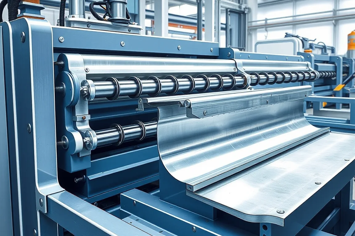
Automotive roll-forming tooling must produce the specified component repeatedly while preserving the features that matter in its final assembly. Roller count and machine length do not describe that capability by themselves. A useful tooling review connects the drawing, material envelope, forming sequence, secondary operations and acceptance method.
Start with the controlled component definition
Use the current drawing revision and identify the functional dimensions, measurement datums and mating interfaces. Include holes, slots, joining edges, cut ends and any local features made outside the roll former. A clean nominal cross-section is insufficient when the actual component contains additional operations.
Distinguish an open formed section from a welded or otherwise closed part. If joining changes the final geometry, the tooling discussion must cover the finished route. Approval of the section before joining does not automatically establish the shape of the completed component.
Specify material combinations rather than isolated limits
List the intended grades, thicknesses, coating conditions and strip widths together. A tool set demonstrated at one grade and thickness should not be assumed to cover a different combination simply because both values appear somewhere in a brochure. Ask which cases represent the design boundaries.
Record how incoming material is identified and checked during development. A change in strip condition can affect the observed result, so setup corrections should not be attributed to tooling alone without confirming the material used in the trial.
Review how the shape develops through the passes
The forming sequence progressively develops the cross-section. Its review should explain when important bends are introduced, how the strip is supported and how the intended edge relationships are maintained. Ask how the sequence addresses difficult returns, asymmetric features and operations performed before or after forming.
The buyer does not need to approve every proprietary tool dimension to ask for a clear development and validation plan. Focus on the design risks, representative trial material, measurement method and evidence that the final part meets the agreed requirements.
Treat springback as a material-and-geometry problem
The relaxed part must meet its drawing after it leaves the tooling. Measuring a section while restrained in a stand can hide the shape that will appear at discharge. Agree when and how the part is supported for inspection, and use the same method throughout development.
Where material variants produce different relaxed shapes, ask how settings or tooling changes are controlled. A trial record should identify the relevant recipe and material, not describe a correction as a universal solution for all grades and thicknesses.
Coordinate holes and other features with forming
Pre-pierced and post-formed features create different access and registration questions. Establish the final feature datums and examine whether forming changes the local condition around them. A hole that is correctly positioned in flat strip still needs to be checked in the finished component.
Include the end relationship. A regular pitch can be correct while the first or last feature is misplaced relative to the cut end. Acceptance should inspect representative short and long parts, changeovers and any special end pattern used by the project.
Separate forming tools from cutoff and joining tools
The roll set is only part of the tooling scope. Cutting may need profile support, and downstream joining may need fixtures or additional controls. Identify which tools produce a complete part and which are excluded from the quotation or installed elsewhere.
Inspect the cut end separately from the middle of the profile. Local distortion, burrs or inconsistent preparation can prevent an otherwise correct section from fitting its next operation. A full-route sample is more informative than a long uncropped demonstration strip.
Design the change strategy around actual part families
Shared equipment can use adjustments, replaceable components or larger tooling exchanges. Ask for a part-to-tool matrix showing what changes between approved variants. Similar outside dimensions do not establish that the same forming, piercing and cutoff tools are suitable.
Record setup references, tool identification and the first-part checks required after an exchange. The practical benefit of modular tooling depends on repeatable recovery, storage and handling as well as the time needed to move the tool assembly.
Plan inspection before the tools are accepted
Agree which dimensions will be checked routinely and which require more detailed evaluation. Include the measurement supports, gauges and sample locations. A tool acceptance record should connect each important characteristic to a method and an agreed result rather than relying on a general statement that the part looks correct.
For assembly-related features, use controlled mating references where appropriate. Easy assembly is useful evidence, but it does not replace the required dimensional or material checks. Keep component geometry separate from vehicle-level performance conclusions.
Control wear, repair and development changes
Keep tool identities and revisions traceable to the approved part setup. A repair or replacement should be followed by the required checks before the equipment resumes accepted production. Record whether the change affects only one component or the wider forming sequence.
Ask what documentation is supplied for setup, inspection, service and replacement tooling. Clear records reduce dependence on undocumented operator memory. They also make it easier to investigate a later dimensional drift without reconstructing every development decision from scratch.
Build a meaningful tooling trial
Select representative normal cases and the important boundary combinations. Include feature-rich parts, required joins and cut ends. Demonstrate the relevant changeovers and retain accepted samples with their material identities and setup references.
The trial should finish with a defined list of results, unresolved items and any agreed follow-up. Avoid accepting a different material or simplified section as proof for the original component unless the difference is explicitly evaluated. Tooling validation is strongest when the sample corresponds to the part that will actually be ordered.
Frequently asked tooling questions
Does a greater number of forming stands mean better tooling?
Not by itself. The sequence must suit the component and material. Evaluate accepted geometry, surface condition and repeatability rather than using stand count as a quality score.
Can one tool set cover several material grades?
Possibly, but the combinations and required settings must be demonstrated. Do not infer a complete envelope from separate successful trials at unrelated limits.
Should holes be checked before or after forming?
Final acceptance must address the finished component's feature locations and condition. Intermediate checks can help control the process but do not replace the final datum requirements.
What belongs in the tooling handover?
Approved part and tool identities, setup references, demonstrated material combinations, inspection methods, retained samples and service information. Include the process for evaluating repaired or replacement tools.
Continue your research
- Automotive Roll Forming Machines
- Automotive Bumper Beam Roll Forming Machine
- Automotive Door Beam Roll Forming Machine
- Automotive Seat Rail Roll Forming Machine
- Automotive Window Guide Channel Roll Forming Machine
- Heavy Truck Side Member Roll Forming Machine
- How Automotive roll forming machine Works
- How To Choose a Automotive roll forming machine
- Automotive roll forming machine Price: What Affects the Cost?