
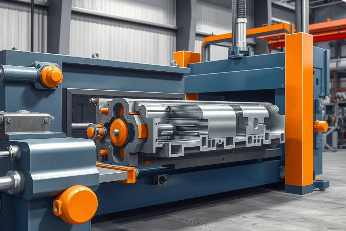
Tooling for a sandwich panel line must be reviewed as part of the complete panel construction. Facing rolls define metal geometry, but panel thickness, joint alignment, core preparation, cutting and support also determine the finished result. A successful isolated facing sample is not proof that the assembled panel will meet its drawing.
Start with the complete panel section
Show upper and lower facings, core geometry, overall thickness and the joint between neighboring panels. Identify functional datums and any seals, fastening recesses or local details. Keep facing-metal thickness separate from the overall panel dimension.
Use controlled drawings for every required variant. Similar exterior appearance can conceal different edge or core requirements. The tooling proposal should state which combinations it covers and what changes between them.
Review upper and lower facing tools separately
The two facings may use different profiles, finishes and edge geometry. Identify the material and exposed surface for each route. Ask how tooling and contact arrangements preserve the required shape and appearance through production.
Trial relevant material combinations rather than assuming a single facing sample represents all finishes and thicknesses. Keep the accepted material, tool and setup identities with the inspection record so that the result can be reproduced.
Design around the assembled joint
The panel edge must work with its counterpart after the facings and core are combined. Review the relationship between the formed metal and the intended core or recess geometry. Overall width alone does not describe this interface.
Assemble representative panels and inspect engagement, alignment and visible edge condition. Record forcing or local rework. A joint that connects only after trimming or reshaping is not the same as repeatable accepted production.
Coordinate forming with the core route
The facing tools should be considered alongside the selected core preparation and bonding arrangement. Identify where the materials meet and how the proposed route maintains their intended relationship. Different core systems can require different equipment and setup considerations.
Use the responsible material and equipment suppliers' validated process requirements. The tooling review should make interfaces clear, not substitute guessed process settings for the specific panel system.
Control thickness and alignment through the panel process
Ask how the equipment establishes and checks the required panel geometry during the relevant process stage. Review width, overall thickness, facing alignment and edge consistency. A correct roll-formed facing can still be part of an incorrectly assembled panel.
Define the measurement condition for final inspection, including support and any required release timing. Keep in-process checks distinct from the final panel acceptance method so that results from different stages are not confused.
Include profile and thickness changes in the tool matrix
List the tools, supports, guides or other components that change for each panel family. Include the upper and lower facing routes, joint details and cutoff requirements. A nominally adjustable main section does not establish that every surrounding operation is adjustable in the same way.
Demonstrate the important transitions through the first accepted new panel. Record startup waste, inspection and correction work. That evidence is more useful than timing only the visible mechanical adjustment.
Review cutting tools through finished-end quality
Cutting affects both facings and core. Specify the required end condition, squareness and length accuracy for representative formats. Identify the supporting, waste-handling and extraction arrangements included with the cutting method.
Inspect both ends and the adjacent joint areas after the full operation. A satisfactory central panel section can coexist with unacceptable local damage. Keep cutoff acceptance connected to the delivered panel rather than treating it as a separate cosmetic issue.
Protect surfaces and edges during handling
Supports, transfer points and stacking arrangements need to suit the panel's length, surfaces and joint details. Review where loads and restraints contact the product. An exposed facing or projecting edge may require a different handling strategy from a flat robust panel.
Retain samples after normal packing and movement. Comparing their condition with samples at the line exit helps identify damage introduced downstream. The tooling and handling package should support the agreed saleable-panel condition.
Plan inspection and service references
Identify the gauges, drawings and sample references used to restore an accepted setup. Keep tool identities and revisions connected to the approved panel matrix. Repairs and replacement components should be followed by the relevant checks before normal release resumes.
Ask what documentation and training accompany the equipment. A repeatable process depends on controlled setup and inspection, not only on the experience of the person who performed the original demonstration.
Validate a representative panel set
Include normal products, important boundary combinations and relevant changeovers. Check dimensions, joint fit, surfaces, cut ends and the product-specific bond requirements. Retain materials and process records with the accepted samples.
Keep manufacturing validation distinct from wider structural, thermal or fire-related claims. Tooling can demonstrate the defined production result, but the finished panel or assembly needs the appropriate evidence for any performance classification claimed later.
Frequently asked tooling questions
Can facing rolls alone validate a panel?
No. The complete construction includes core, bond, joint, thickness control and cutting. Evaluate the assembled panel through the required route.
Does one joint drawing cover every thickness?
Do not assume so. Review the actual panel matrix and identify the components and settings needed for each approved combination.
Why inspect after packaging?
Handling can change surface and edge condition after successful forming. The delivered panel should retain the quality established by the production trial.
What should a tool-change demonstration include?
All relevant component changes, setup recovery, inspection and the first accepted new panel. Include waste and elapsed time, not only movement of the main adjustment mechanism.
Continue your research
- Sandwich Panel Production Lines
- EPS Sandwich Panel Production Line
- Rockwool Sandwich Panel Production Line
- EPS Wall Sandwich Panel Production Line
- EPS Roof Sandwich Panel Production Line
- Rockwool Wall Sandwich Panel Production Line
- How Sandwich panel production line Works
- How To Choose a Sandwich panel production line
- Sandwich panel production line Price: What Affects the Cost?