
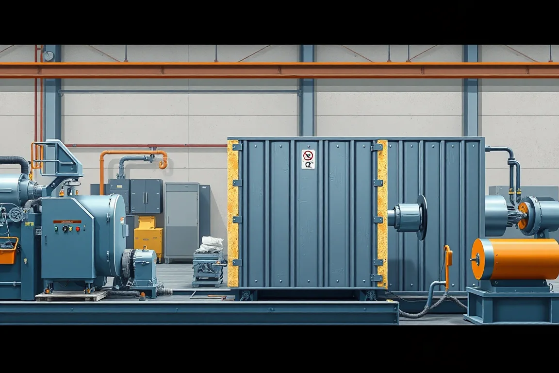
A sandwich panel production line combines facings and an insulating core into a finished composite panel. Metal profiling is only one part of that route. The core system, bonding process, panel geometry, cutting and handling must be coordinated, so a single-skin roof-sheet roll former should not be confused with a complete insulated-panel line.
Define the panel before describing the line
Start with the complete panel drawing: upper and lower facings, core type, overall thickness, width, edge joint and finished length. Identify whether the panel is intended for a wall, roof, cold-room enclosure or another application. Similar outside dimensions do not establish identical production requirements.
Keep metal-facing thickness separate from overall panel thickness. Record the facing material and finish on each side. A panel can use different requirements for its exposed face and internal face, and the production brief should preserve that distinction.
Distinguish continuous and batch production
Continuous arrangements move the panel construction through coordinated operations, while discontinuous arrangements process individual panels or batches through the defined cycle. The appropriate route depends on the product, core system, formats and expected order mix.
Compare the complete production boundary rather than assuming one label guarantees flexibility or capacity. Ask how the proposed arrangement handles length changes, thickness changes, special formats and any inserts required by the panel design.
Prepare the facings and their edge geometry
Metal facings may be supplied from coils and profiled to create the required surface and edge details. Their alignment matters because the assembled panel must maintain its width and joint geometry. Review the top and bottom facing routes separately where their profiles differ.
Inspect finish after the actual contact and handling sequence. A cosmetic face can be damaged before the core operation begins. Record which surface is exposed, where protective film is used and what condition is required at the final inspection point.
Match core preparation to the selected panel system
Foam-based and preformed-core routes require different preparation and process arrangements. A line proposed for one core system should not be assumed to cover another through a simple setting change. Identify the materials and operations actually included.
For the chosen route, obtain the responsible material and equipment suppliers' process requirements. This guide does not provide a chemical recipe or operating temperature schedule. Those settings must come from the validated materials, equipment and procedures for the specific panel.
Coordinate bonding and panel geometry
The process must combine the facings and core while controlling the intended thickness, alignment and bond condition. The proposal should explain how the panel is supported and constrained through the relevant stage, and how a change in panel format is managed.
A visually complete panel is not sufficient evidence of the bond throughout its area. Agree the inspection and test methods appropriate to the product. Keep process settings and material identities linked to the samples used for acceptance.
Preserve the joint and edge details
Panel joints affect how neighboring panels fit and how the enclosure is assembled. Show the complete edge drawing, including any relevant recesses, seals or fastening features. Do not evaluate the joint from nominal overall width alone.
Assemble representative panels during trials. Check alignment, engagement and the relationship between facings and core at the edges. Any forcing, trimming or local repair should be recorded rather than hidden in an apparently successful demonstration.
Cut panels to the required order schedule
The cutoff produces finished lengths from the panel route. Review squareness, cut-end condition and the effect on facings and core. The equipment and extraction or waste-handling scope should match the selected materials and cutting method.
Trial representative short and long panels rather than one convenient length. A good central panel section does not establish acceptable cut ends or accurate order lengths. Keep length identification connected to the finished pieces.
Handle the panel through its release condition
Panels may require defined conditions or time before particular handling, stacking or dispatch steps. Follow the validated process requirements for the selected system. Do not infer that a panel is ready for every later operation merely because it has left the main line.
Inspect after normal movement and packaging. Long panels, visible facings and joint edges can be affected by supports and restraints. Acceptance should describe the delivered panel condition as well as the appearance at the production exit.
Track materials and production changes
Keep facing coils, core materials and other relevant inputs traceable to the production batch. Record changes of thickness, width, finish and core system. This information is useful when a defect appears only in a particular portion of the run.
Include startup, transition and rejected panels in the production report. They consume material and time even though they are not accepted output. A capacity demonstration should show how the normal order mix moves through these transitions.
Validate the complete product and process
Agree dimensional, bond, surface, joint and handling checks with the responsible technical parties. A machine trial demonstrates the specified manufacturing result; it does not automatically establish every fire, structural or thermal claim for a building assembly.
Separate those performance requirements and their evidence from routine production checks. The useful handover includes the panel specification, material scope, approved process references, inspection methods and the unresolved items that still require verification.
Frequently asked process questions
Is a sandwich panel line just two roll formers?
No. Facing preparation is only part of the route. Core preparation, bonding, geometry control, cutting and handling are essential to the complete panel system.
Can one line make every core type?
Do not assume so. The proposal must identify the core systems, equipment changes and validated processes included. Different core routes can require substantially different operations.
Why test assembled joints during a trial?
Separate panel measurements may not reveal how neighboring pieces engage. Representative assembly helps evaluate the actual edge relationship alongside the required dimensional checks.
Does an acceptable panel prove a fire rating?
No. Product and assembly performance claims require the applicable evidence for the specified construction. Routine manufacturing acceptance is a different question.
Continue your research
- Sandwich Panel Production Lines
- EPS Sandwich Panel Production Line
- Rockwool Sandwich Panel Production Line
- EPS Wall Sandwich Panel Production Line
- EPS Roof Sandwich Panel Production Line
- Rockwool Wall Sandwich Panel Production Line
- How To Choose a Sandwich panel production line
- Sandwich panel production line Price: What Affects the Cost?
- Materials and Thickness for Sandwich panel production line