
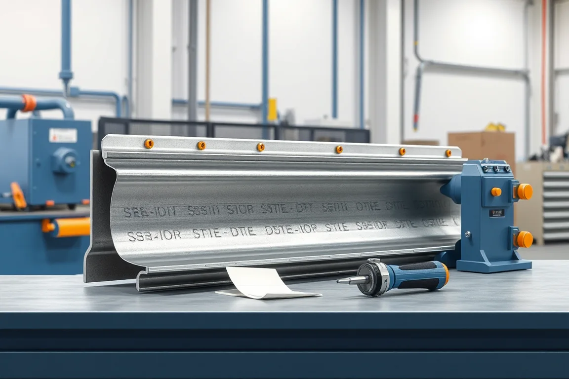
Choosing an automotive roll forming machine starts with the part, not the machine. The controlled drawing defines section geometry, material grade, thickness, hole patterns, joining flanges and assembly interfaces. The validation plan defines which dimensional and functional characteristics must be met and how they are measured. The machine is then selected to reproduce those characteristics reliably at the required accepted output. A general roll forming capability does not demonstrate compliance with an OEM part or crash requirement. This article explains the decisions, trade-offs and evidence that matter.
Start With the Part Drawing and Validation Plan
The drawing revision is the anchor for every later comparison. It sets the datum scheme, the tolerances that govern fit and function, and the features that must be produced in the forming line rather than in secondary operations. The validation plan adds the level of evidence expected: dimensional layout, material certificates, forming simulation or trial results, and downstream joining trials. Before comparing machines, confirm that every supplier is quoting against the same drawing revision and the same material envelope. A quote that assumes a different grade or thickness is not comparable.
Production volume expectation also belongs here, because it changes how much automation is justified. Low-volume programs with several variants reward quick changeover and simple tooling access. High-volume programs with a stable part family reward integrated operations and automated handling. Neither is universally better; each matches a different production pattern.
Forming Sequence and Machine Interfaces
Roll forming is a continuous sequence: coil is fed and leveled, the strip passes through a series of forming stations that progressively bend the section, then features are pierced, cut or joined, and the finished part is discharged. Each station adds a small amount of bend until the final section is reached. The number of stations and their arrangement depend on section complexity, material strength and the required surface quality.
Interfaces matter as much as the forming stations. The feed and leveling section determines how consistently material enters the first forming pass. The cut-off and feature operation determines end quality and hole position. If joining such as welding or clinching is integrated, the machine layout must accommodate it without disturbing the formed section. Discharge and stacking affect whether parts reach inspection undamaged.
Material and Thickness Decisions
Automotive steel grades range from mild to advanced high-strength steels, and each behaves differently in forming. Higher-strength material needs more forming force, can exhibit greater springback, and may require more stations or different roll design. Thickness is specified on the drawing, and the operating range of the machine must be verified by the supplier against the actual grade and thickness combination. A wide nominal thickness range on a brochure is not a substitute for verification with the specific material.
Material consistency from the coil supplier also affects forming stability. Coil-to-coil variation in yield strength or coating can change springback and surface finish. The selection process should identify how incoming material is checked and how deviations are handled. This is a production control question, not only a machine capability question.
Profile Complexity, Datums and Measurement
Section geometry determines tooling complexity. A simple open channel with generous radii is easier to form than a closed or multi-flange section with tight tolerances and critical flat areas. The datum scheme on the drawing tells where measurements are taken; it must be reflected in the gauges or fixtures used for acceptance. Without agreed datums, two parties can measure the same part and disagree.
Measurement method and acceptance criteria should be agreed before tooling approval. This includes the instruments used, the frequency of checks, and how springback, twist and camber are evaluated. A roll-formed safety-related component is not validated simply because the section matches a drawing; vehicle-level performance requires separate engineering and testing.
Cutting, Piercing and Secondary Operations
Cutting in a roll forming line can be done by shear, saw or other methods, depending on section and end-quality requirements. The cut must be supported by the profile so the section does not collapse, and the cut length must be accurate enough for downstream assembly. Piercing and notching are usually integrated to avoid a second handling step, but they add tooling complexity and must be located relative to the forming datums.
Secondary operations such as sweeping, bending or tapping can be integrated or left offline. Integration reduces handling and work in progress, but makes the line less flexible and increases changeover time. Offline operations are simpler to change but add labor and inventory. The right choice depends on the product mix and volume pattern.
Cut-Off, Joining and Assembly Interfaces
The cut-off method and the joining process must be considered together with the assembly interfaces. If the part is welded or riveted into a larger body structure, the flange geometry and hole positions must align with the mating component. Joining processes such as spot welding, laser welding or clinching each have different tolerance and access requirements. A machine that forms well but cannot present the part correctly to the joining operation will create problems downstream.
Joining is also where heat input can affect material properties. Welding on high-strength steel may require specific controls; this is a process engineering question that must be validated with the actual material and part configuration. The machine selection only sets the stage.
Output: Define Accepted Parts per Shift
Output should be defined as accepted parts per shift for the actual profile and material, not as a theoretical line speed. Line speed is one input, but the sustainable rate depends on changeover, feature operations, joining, inspection frequency and downtime. A meaningful output estimate accounts for the real production pattern.
The buyer should ask how the proposed line reaches the required accepted output and what assumptions are made. If the quote depends on equipment outside the line, such as a separate welding cell, include that equipment in the comparison. Otherwise the output claim is incomplete.
Automation, Changeover and Product Mix
Automation levels range from manual coil loading and part removal to fully automated lines with automatic tooling change. Automation raises initial cost and maintenance complexity but can reduce labor and improve consistency in high-volume production. For a mix of several similar profiles, quick-change tooling and preset station positions can reduce changeover time. For a single high-volume profile, dedicated tooling and automated handling may be more appropriate.
The product mix should be stated as a range of profiles, materials and thicknesses. The machine must be able to change over between them without excessive trial and scrap. A demonstration of changeover on the intended product mix is more informative than a general capability statement.
Spare Parts, Maintenance and Service Access
Roll forming lines run for years, and maintenance access affects uptime. Stations should be reachable for roll inspection and replacement. Hydraulic, electrical and control components should be arranged so that fault finding is practical. Spare parts availability and recommended spares lists should be part of the quote scope. A machine that is difficult to maintain will eventually reduce accepted output.
Quote Scope and Accepted-Output Cost
Quotes are not comparable unless the scope is aligned. A complete quote should state what is included: coil handling, forming stations, feature operations, cut-off, joining, discharge, controls, safety systems, installation, commissioning, training and documentation. It should also state what is excluded, such as foundations, utilities, compressed air, offline equipment or special packaging.
Accepted-output cost is the more useful economic comparison. It combines the quoted scope with the realistic accepted parts per shift, material utilization, expected scrap, changeover losses and maintenance. A lower initial price can become more expensive if it requires more operators, produces more scrap or cannot reach the required output. Because no prices are given here, the method is to build the comparison from the supplier's own scope and the buyer's production data.
Comparison of Alternatives: Dedicated versus Flexible Lines
A dedicated line is tooled for one profile family and one material envelope. It can be simpler, faster and more consistent for that specific part, but it is not easily repurposed. A flexible line includes adjustable or quick-change tooling and can run several profiles, but it may have more setup complexity and slightly lower peak rate. The trade-off is between volume stability and product variety.
Another alternative is a line with integrated joining versus one that forms only. Integrated joining reduces handling and improves dimensional control through the joining step, but it adds complexity and may limit access for maintenance. A form-only line is simpler but requires a separate joining operation and more part handling.
Troubleshooting Symptoms and Diagnostic Evidence
Common forming symptoms include twist, camber, bow, edge wave and incorrect flange angle. These usually point to roll setup, material variation or station alignment. Diagnosing them requires evidence: coil material certificates, strip width and thickness measurements, roll gap records, and dimensional inspection against the drawing datums. The goal is to trace the symptom to a specific cause without adjusting moving machinery unless the proper procedure and authority are in place.
Cut-off symptoms include burrs, deformation at the cut and length variation. Piercing symptoms include hole position error and slug retention. Joining symptoms include weak welds or distortion. Each requires its own evidence: tool wear records, force or energy logs, and inspection of the affected feature. A controlled diagnostic process is safer and more effective than trial-and-error adjustment.
Practical Selection Checklist
- Confirm the drawing revision, datum scheme and acceptance criteria.
- State the actual material grade, thickness and coating for each profile.
- List the required operations: forming, piercing, cut-off, joining, secondary.
- Define accepted output per shift for the real product mix.
- Agree on measurement method and inspection frequency before tooling approval.
- Compare quotes against the same scope: included and excluded items.
- Request trial or simulation evidence for the actual material and part.
- Review changeover demonstration for the intended product mix.
- Include spare parts, maintenance access and training in the comparison.
FAQ
What should be agreed before tooling approval?
Before tooling approval, agree the drawing revision, datum scheme, measurement method and acceptance criteria. Also confirm the material and thickness envelope and the operations to be performed in the line. Without these agreements, tooling may be built to assumptions that do not match the part or the validation plan.
Can a general roll forming machine make automotive parts?
A general machine can form a section, but automotive parts often require documented dimensional control, material traceability and validation. The machine must be capable of reproducing the required features within tolerance using the actual material. A general capability statement does not demonstrate that the machine can meet the part-specific requirements.
How is output best defined for an automotive roll forming line?
Define output as accepted parts per shift for the actual profile and material, including realistic changeover, feature operations and inspection. Theoretical line speed is only one input. The buyer should ask the supplier to explain how the proposed line reaches the required accepted output and what assumptions are made about uptime and scrap.
Why does material grade affect machine selection?
Higher-strength steels require more forming force, can spring back more, and may need different roll design or more stations. Thickness and coating also affect friction, surface finish and tool wear. The machine's operating range must be verified by the supplier against the specific grade and thickness combination, not just a nominal range.
What does a complete quote include?
A complete quote states what is included and excluded. Typical inclusions are coil handling, forming stations, feature operations, cut-off, joining, discharge, controls, safety systems, installation, commissioning, training and documentation. Exclusions may include foundations, utilities, offline equipment or special packaging. Comparing quotes with different scopes can be misleading.
How should troubleshooting be approached?
Troubleshooting should be evidence-based. Gather material certificates, dimensional inspection results, roll setup records and tool wear data. Match the symptom to the likely cause, such as twist from roll alignment or camber from material variation. Do not adjust moving machinery without the proper procedure and authority; focus on diagnosis and controlled correction.
Continue your research
- Automotive Roll Forming Machines
- Automotive Bumper Beam Roll Forming Machine
- Automotive Door Beam Roll Forming Machine
- Automotive Seat Rail Roll Forming Machine
- Automotive Window Guide Channel Roll Forming Machine
- Heavy Truck Side Member Roll Forming Machine
- How Automotive roll forming machine Works
- Automotive roll forming machine Price: What Affects the Cost?
- Materials and Thickness for Automotive roll forming machine