
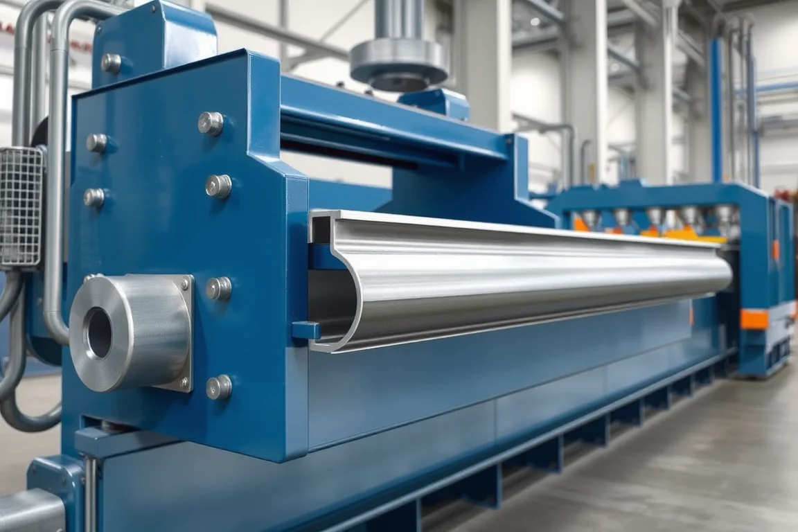
An automotive window guide channel is not a generic open section. It is a functional interface component that locates and supports the glass edge, retains or cooperates with seals, and often sits behind trim or weatherstrip lips. The roll forming machine therefore has to reproduce a controlled drawing: section geometry, datum scheme, holes, joining flanges, and the surfaces that contact glass, seal and trim. This page explains how those requirements translate into production route decisions, where forming ends and assembly begins, and how acceptance should be structured.
What the window guide channel actually does in the door
The channel guides the glass as it moves and helps control its lateral position, so small deviations in bend position or flange angle can change how the glass seats against the seal. The inner surfaces matter because they run against the glass edge or a liner. The outer surfaces matter because they may clip into a weatherstrip, meet a belt molding, or be welded or riveted to a bracket that ties the channel to the door frame. Two channels from the same tool set can perform differently if the coil, coating or springback varies between lots.
This is why the part should be described by function as well as by section. A drawing that only fixes the outside profile but leaves the datum scheme and joining flanges vague invites disputes during tooling approval.
Profile geometry and the interfaces that drive tooling
Several features directly influence forming difficulty. Local bends along the channel length, such as a swept bend to follow the door curvature, are usually produced by sweep or stretch-bend operations after forming rather than by the forming passes alone. Holes and slots for clips, fasteners or locating pins must be pierced or punched at positions that remain accessible after the section closes. A hem or closed lip may require a separate closing pass with careful control of edge position. Where the channel joins a bracket or end cap, the joining flange must be wide enough and flat enough for the chosen joining method.
Surface condition is another interface. Coated or pre-painted stock can be marked by aggressive roll contact; the same pass design that works for bare steel may not be acceptable for a coated surface that will remain visible.
Material assumptions and forming behavior
The material should be specified by the drawing: grade, strength, coating and allowable variation. Higher-strength steel generally requires different bend radii, pass development and springback compensation than mild steel, because the elastic recovery after each bend is greater and the forming window narrows. The same roll set cannot be assumed to run every grade at every thickness. Base-metal thickness and grade are buyer inputs; an operating range on any machine requires supplier verification against the actual profile.
Where the forming simulation or trial evidence exists, it helps to see how the material behaves at the critical bends, especially near holes where local strain concentrates.
Production route: from coil to verified channel
The route usually follows a sequence: traceable coil feed, precision forming, feature and cut operations, joining, then dimensional verification. Each stage has a different owner and a different acceptance method. Coil feed and forming are part of the machine scope. Feature operations such as piercing, notching or slotting may be integrated into the line or moved offline. Cutoff must be profile-supported so the cut does not crush or twist the section; cut length, end quality and any secondary end operations should be confirmed.
Joining is often where the route decision becomes commercial. Welding, riveting, clinching or adhesive bonding can be in-line or off-line, and the choice affects fixture design, cycle time and the amount of handling damage the part receives.
Where forming stops and assembly begins
Forming produces a channel with a defined cross-section and length. Assembly produces a finished window guide that can be installed. The boundary between them should be written down. If brackets, end caps, weatherstrip retention features or mounting clips are added after forming, those operations need their own fixtures, gauges and traceability. A common failure mode in project planning is to assume the roll forming machine delivers an installed part, when in fact several secondary operations remain.
Certification and in-service performance sit outside the machine scope. Vehicle-specific durability, glass function and seal compatibility belong to the part approval plan, not to the forming equipment supplier.
Inspection strategy at the machine and at the part
Inspection should start with the drawing datums. Measurement method matters: a section measured with a calliper at a random point may not compare meaningfully with a drawing that defines a datum feature. First-off pieces and a representative steady-production sample should be checked with the agreed gauges. Critical features include flange angles, bend positions, hole locations, cut length and end condition.
Assembled alignment should also be reviewed, because a channel that meets the section but distorts during joining will still cause a fit problem. The practical sequence is to trial the intended liner and mating parts using the approved component geometry, then evaluate joints and cut ends as well as the section.
Comparing production alternatives
Roll forming is one route among several. Press brake forming can handle low volumes and simple bends, but it is slow for long channels and offers less consistency on bend position. Extrusion suits constant sections in aluminium or polymer but not the mixed joining flanges and local features typical of a steel guide channel. Stamping and welding can produce complex local shapes, but the tooling cost and cycle time differ, and weld distortion must be managed.
Roll forming is usually chosen where the section is long, the features are distributed along the length, and repeatability matters. The comparison should be based on the part drawing, annual volume, material and the finishing operations required, not on forming method alone.
Practical checklist before tooling approval
- Is the part drawing complete with datums, joining flanges and interface surfaces?
- Are material grade, coating and thickness variation specified by the buyer?
- Are local bends, sweep or stretch-bend operations identified as in-line or off-line?
- Are piercing, notching and slotting positions accessible after forming?
- Is cutoff profile-supported, and are cut length and end quality defined?
- Are joining methods and their fixtures included in the scope?
- Are first-off and steady-production gauges agreed before tooling approval?
- Is assembled alignment included in the acceptance review?
Electrical supply and installed power
The buyer should state voltage, frequency and phase. Installed power is not a single number to copy from a similar project; it requires a confirmed equipment schedule covering the forming drive, any in-line joining, hydraulics and control systems. Quotation scope should distinguish production hardware from part-validation responsibilities.
Frequently asked questions
Can one roll forming machine produce both left and right window guide channels?
It can if the tooling is designed for the pair and the changeover procedure is defined. Some lines run mirrored profiles with a tooling change; others use dedicated passes. The decision depends on volume balance, setup scrap and how much handling the parts tolerate. The drawing should show whether the parts are true mirrors or share common features.
Why does the same roll set behave differently with a different coil lot?
Yield strength, coating thickness and residual stress vary between lots. Those variations change springback, so bend angles and flange positions shift. A machine that ran acceptably on one lot may need adjustment or a wider forming window for another. This is why the actual material should be used in trials rather than an easier substitute.
How should holes and slots be positioned relative to the datums?
They should be dimensioned from the same datums used for assembly, not from an arbitrary edge. Piercing tools are built to those positions, and inspection should use the same scheme. If a hole moves after joining, the root cause is usually fixture constraint or material movement rather than the piercing station alone.
What does profile-supported cutoff actually change?
It means the cut is taken while the section is internally or externally supported, which reduces collapse, twist and burr formation at the cut end. Without support, a thin or open channel can deform. The requirement should be confirmed against the actual section and the end condition the drawing allows.
Is in-line welding always preferable to off-line joining?
No. In-line joining reduces handling and can improve position consistency, but it adds tooling, controls and maintenance to the line. Off-line joining can be more flexible for low volumes and easier to validate separately. The choice should follow the joining method, volume and how much distortion the part can tolerate.
What should be inspected on the first off and on steady production?
First-off inspection should cover all drawing datums, critical bend positions, hole locations, cut length and end condition. Steady-production checks should watch for drift in those same features, plus surface condition and any signs of tool wear. Assembled alignment should be verified with the mating parts where the drawing makes that possible.

Continue your research
- Automotive Roll Forming Machines
- Automotive Bumper Beam Roll Forming Machine
- Automotive Door Beam Roll Forming Machine
- Automotive Seat Rail Roll Forming Machine
- Heavy Truck Side Member Roll Forming Machine
- Trailer Side Wall Post Roll Forming Machine
- How Automotive roll forming machine Works
- How To Choose a Automotive roll forming machine
- Automotive roll forming machine Price: What Affects the Cost?
Configuration & specification inputs
Match the configuration to your section drawing, material and production requirements.
| Parameter | Requirement / confirmation needed |
|---|---|
| Profile geometry | An automotive window guide needs compatibility with glass, seals and trim. Surface condition, local bends and assembled alignment should be included in the process review. |
| Material | Drawing-specified automotive steel or other validated alloy |
| Thickness & grade | Buyer to specify base-metal thickness and grade; operating range requires supplier verification. |
| Process route | Traceable coil feed → precision forming → feature/cut operations → joining → dimensional verification |
| Cutting | Confirm profile-supported cutoff, cut lengths, end quality and any secondary operations. |
| Output | Define accepted output per shift with the actual profile and material. |
| Electrical supply | Buyer to state voltage / frequency / phase. Installed power requires a confirmed equipment schedule. |
| Acceptance | Trial the intended liner and mating parts using the approved component geometry. Evaluate joints and cut ends as well as the section. Keep vehicle-specific durability and functional validation in the part approval plan. |