
What the question really asks
When someone asks how an automotive roll forming machine works, they are usually not looking for a single sentence about bending metal. They want to know how a flat strip becomes a part that meets a drawing, which operations happen inside the line, which happen outside, and where responsibility lies for each interface. This guide answers that by following the material through the process, explaining the engineering purpose of each stage, and showing how to evaluate a proposed line against an actual part.
The physical sequence: from coil to cut part
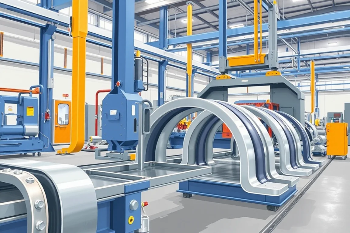
An automotive roll forming line takes a coil of drawing-specified steel and progressively forms it into a constant or variable cross-section. The sequence typically begins with coil loading and feeding, where the strip is uncoiled, straightened if needed, and fed at a controlled rate. The strip then passes through a series of forming stations, each containing rolls that bend the material incrementally toward the final profile. After forming, the line may perform piercing, notching, bending or embossing, then cut the profile to length. Downstream, the cut part may be joined to other components, inspected dimensionally, and released to assembly.
Each of these steps is a process boundary. The way they are integrated—or separated—determines the line's footprint, tooling cost, changeover time and the risk of dimensional drift. A machine that forms and cuts in one continuous flow is different from one that forms coil into a continuous profile that is later cut and joined on separate equipment. Both are valid, but they serve different production strategies.
Coil feed, straightening and material handling
The coil feed system sets the material's position and tension before forming begins. Automotive profiles are often made from high-strength steels or coated materials where flatness, camber and edge condition matter. A straightener may be used to remove coil set, but its settings depend on the material grade and thickness. The feed system must also provide reliable strip tracking; if the strip wanders laterally, every downstream station will produce inconsistent geometry.
This stage is also where traceability begins. A line that records coil identity and process parameters supports later investigation if a dimensional or surface issue appears. The interface between the feed system and the first forming station is critical: any mismatch in strip alignment or tension can show up as twist or bow in the finished profile.
Progressive forming stations and roll tooling
Forming stations are where the strip's cross-section is developed. Each station contains a pair of rolls that progressively bend the material. The number of stations and the roll design depend on the profile complexity, material strength and thickness. For automotive parts, the forming process must control springback, which is the elastic recovery of the material after bending. Springback varies with material grade and thickness, so tooling designed for one material may not produce acceptable geometry in another without adjustment or rework.
The forming sequence also determines whether critical features such as holes, notches or flanges can be created without distortion. Some profiles require a pre-pierce station before forming, while others can be pierced after forming. The choice affects tooling complexity and the risk of hole deformation. A practical way to assess a proposed forming line is to review the station-by-station forming simulation or trial evidence for the actual material and part configuration.
Feature operations: piercing, notching, bending and embossing
After the main forming stations, the line may perform secondary operations that add features to the profile. Piercing creates holes for fasteners, welding or locating. Notching removes material to allow bending or to create clearance. Bending may be used to form flanges or end details that cannot be produced by the main rolls. Embossing can add stiffness or create a locating feature.
These operations are often integrated into the line to reduce handling and improve dimensional consistency. However, they also add tooling cost and require careful synchronization with the forming speed. If a feature is created after cutting, the part must be re-referenced, which introduces a new datum scheme. The quotation should clarify whether each feature is performed in-line or off-line, and who is responsible for the tooling and the interface.
Cutoff and end quality
The cutoff station separates the formed profile into discrete parts. For automotive applications, the cut must be clean and repeatable, with minimal burr and no distortion of the profile cross-section. The cutting method—such as shear, saw or laser—depends on the material, thickness and required end quality. A profile-supported cutoff can help maintain shape during cutting, especially for thin or high-strength materials.
Cut length accuracy is another consideration. The cutoff system must be synchronized with the feed rate to achieve the specified length. If the part requires secondary operations after cutting, the cut end may need to be used as a reference for those operations. This creates an interface between the cutoff station and any downstream equipment.
Joining: where the line ends and assembly begins
Many automotive roll-formed parts are not finished components on their own. They may be joined to other roll-formed sections, stampings or castings to form a structural assembly. Joining methods include spot welding, laser welding, riveting, clinching or adhesive bonding. Some lines integrate joining stations, while others produce cut parts that are joined in a separate cell or at a supplier's facility.
The decision to integrate joining affects the line's complexity and the part's dimensional stack-up. If joining is performed in-line, the line must control the position of both mating parts. If joining is off-line, the cut parts must be handled and re-referenced, and the joining process becomes a separate manufacturing step with its own tooling and validation. The quotation should clearly state which operations are included and which are not.
Dimensional verification and acceptance
Dimensional verification confirms that the formed and cut part meets the drawing requirements. It may be performed in-line with sensors or gauges, or off-line in a inspection fixture. The measurement method and acceptance criteria should be agreed before tooling approval. For automotive parts, the datum scheme and measurement points are typically defined on the part drawing. The line's gauge system must be capable of measuring those features without introducing additional variation.
Verification is not limited to the roll forming line itself. If the part is joined or assembled later, the final assembly must also be verified against its own drawing and validation plan. A roll-formed section that matches its drawing does not automatically mean the assembled component meets vehicle-level requirements. Crash performance and durability require separate engineering and testing.
Comparing integration alternatives
Automotive roll forming lines can be configured in several ways. A fully integrated line performs coil feeding, forming, feature operations, cutting, joining and inspection in one continuous sequence. This reduces handling and work-in-progress but increases capital cost and changeover complexity. A partially integrated line may perform forming and cutting in-line, with joining and inspection off-line. This can be more flexible for low-volume or high-variety production. A decoupled approach uses separate machines for forming, cutting and joining, which may suit prototyping or low-volume production where tooling investment must be minimized.
The trade-offs involve capital cost, floor space, labor, changeover time and dimensional risk. Integrated lines tend to have lower labor per part but higher tooling cost and longer changeover. Decoupled lines offer flexibility but require more handling and re-referencing, which can increase variation. The right choice depends on the production volume, part complexity and the maturity of the part design.
Selection checklist for a proposed line
- Identify the input and output of each station in the proposed sequence.
- Distinguish the line's physical sequence from the complete manufacturing route.
- Confirm how the part is referenced after cutting or a secondary operation.
- Clarify which operations are integrated, which are manual and which happen elsewhere.
- Agree datums, measurement method and acceptance criteria before tooling approval.
- Review forming simulation or trial evidence for the actual material and part configuration.
- Confirm access to critical features and whether piercing, welding or sweeping is integrated.
- Ask who supplies tooling for any omitted operation and who is responsible for the interface.
- Validate forming and downstream joining with the actual material and part configuration.
Common symptoms and diagnostic evidence
When a roll forming line produces out-of-tolerance parts, the symptom may be twist, bow, camber, hole distortion or incorrect cut length. Each symptom points to different stages. Twist or bow often relates to strip alignment, forming station setup or material properties. Hole distortion may indicate that piercing occurs at a point where the material is not fully supported. Cut length variation can come from feed synchronization or cutoff timing.
Diagnostic evidence should be gathered without adjusting moving machinery while it is running. Instead, review historical process data, inspect the part against the drawing, and compare the actual forming sequence with the intended sequence. Check whether the material matches the specification and whether the tooling is designed for that material. If a problem persists, a controlled trial with the actual material and part configuration can help isolate the cause. Always follow lockout procedures and never reach into a running line.
FAQ
What is the difference between a roll forming line and a complete manufacturing route?
A roll forming line is the machine that transforms coil into a formed and cut profile. The complete manufacturing route includes all operations needed to turn that profile into a finished component, such as joining, secondary machining, surface treatment, inspection and assembly. Some of these operations may be integrated into the line, while others occur elsewhere. Confusing the two can lead to underestimating tooling and handling requirements.
How do I know if a proposed line can produce my part?
Review the station-by-station sequence against your actual part drawing. Confirm that the forming stations can produce the required cross-section with the specified material and thickness. Check whether feature operations such as piercing or notching are included and whether they are performed before or after forming. Ask for forming simulation or trial evidence for the actual material and part configuration. A general roll-forming capability does not demonstrate compliance with an OEM's part or crash requirements.
Why does material grade matter for roll forming?
Material grade affects springback, formability and the force required to bend the strip. High-strength steels may need more forming stations or different roll designs to achieve the same geometry as mild steel. Coated materials may require careful handling to avoid surface damage. The tooling must be designed for the specific material and thickness range. Using a different material without verifying tooling suitability can lead to dimensional issues or tool wear.
What should be included in a quotation?
A quotation should specify the scope of supply: coil feed, straightener, forming stations, feature operations, cutoff, joining and inspection. It should state which operations are performed in-line and which are off-line. It should define the interface responsibilities for any omitted operation, including tooling supply and part re-referencing. It should also state the acceptance criteria, measurement method and validation plan. Without this clarity, the quotation may not reflect the true cost of integrating the line into your manufacturing route.
How can I troubleshoot dimensional variation without unsafe intervention?
Start by comparing the actual part to the drawing and identifying which dimensions are out of tolerance. Review process data such as feed rate, forming speed and material batch. Inspect the tooling for wear or damage. Check whether the strip is tracking correctly and whether the material matches the specification. If the issue persists, consult the line builder or a qualified engineer. Do not adjust moving machinery while it is running. Use lockout procedures and follow site safety rules.
Why the process boundary matters
Every arrow in the sequence from coil feed to dimensional verification represents a point where the part changes hands, changes reference or changes state. Misunderstanding these boundaries can lead to unexpected cost, quality problems or delays. By walking through the proposed process with one actual drawing and marking every point where the part is gripped, referenced, punched, bent, cut, joined or inspected, you can see where responsibility lies and where risk accumulates. The goal is not to find a universal recipe but to match a specific line configuration to a specific part and production strategy.
Continue your research
- Automotive Roll Forming Machines
- Automotive Bumper Beam Roll Forming Machine
- Automotive Door Beam Roll Forming Machine
- Automotive Seat Rail Roll Forming Machine
- Automotive Window Guide Channel Roll Forming Machine
- Heavy Truck Side Member Roll Forming Machine
- How To Choose a Automotive roll forming machine
- Automotive roll forming machine Price: What Affects the Cost?
- Materials and Thickness for Automotive roll forming machine