
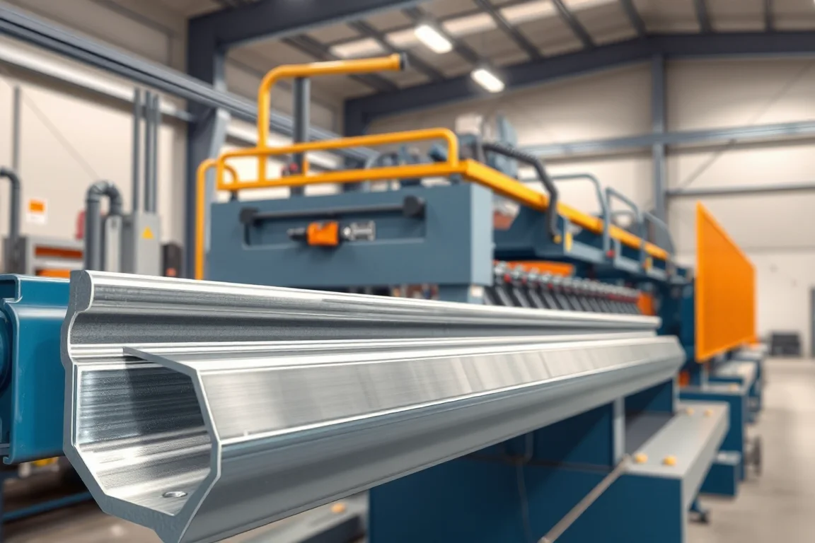
An automotive bumper beam roll forming machine is only one part of a safety-related production system. The finished bumper reinforcement is defined by a vehicle-specific drawing and validation plan, not by a machine category. Roll forming may shape the beam, but material, joining and part acceptance must be agreed separately. This article explains what the machine actually produces, which interfaces matter, how production routes differ, and how to judge output without assuming a general roll forming capability equals compliance.
What the finished profile actually is
A bumper beam is not a single shape. It is a closed or open section that often includes a hat-shaped or multi-corrugated body, attachment flanges, crush features and locating datums. The profile may have stiffening ribs, spot-weld or rivet flanges, and holes for mounting, tow hook access, or sensor brackets. The drawing defines the neutral axis, bend radii, flange angles and the datum scheme used for inspection. Because the beam must transfer crash loads into the vehicle structure, section geometry matters more than surface appearance. A roll forming line produces the formed strip, but subsequent operations create the finished part. The line can cut, pierce, notch, emboss or sweep material, but it does not by itself create a validated bumper reinforcement.
Interfaces that determine whether the line fits the part
The first interface is geometry: the profile must be formable from a flat strip without exceeding material limits. High-strength steel may need larger bend radii or different pass designs to avoid cracking. Springback also changes the final angle, so the line needs either overbending or compensation. The second interface is the joining flange. If the beam is assembled from two or more roll formed pieces, the flange width, hole pattern and surface condition must match the joining method, whether spot welding, laser welding, riveting or adhesive bonding. The third interface is the vehicle attachment. Mounting holes and datum surfaces must be located relative to the vehicle coordinate system, which means the line must hold position and the part must be inspected against the drawing. These interfaces are not optional details; they decide whether the machine can produce a usable part.
Production route: from coil to verified part
The usual route is traceable coil feed, precision forming, feature and cut operations, joining, then dimensional verification. Coil feed must handle the specified material grade, thickness and coating without damaging the surface or introducing edge cracks. Forming happens in a series of stations, each bending the strip slightly until the final profile is reached. Feature and cut operations may include piercing, notching, embossing and cutoff. Joining can occur in-line or offline, depending on the assembly strategy. Dimensional verification uses gauges, fixtures or measurement equipment to confirm the part meets the drawing. Each step adds constraints; for example, piercing after forming may be difficult if the area is hard to reach, while piercing before forming risks distortion. The route should be designed around the actual part, not around a generic machine layout.
Tooling alternatives: solid, cassette and quick-change
Tooling for a bumper beam line usually falls into three practical categories. Solid tooling uses dedicated forming rolls and dies for one profile. It can be robust and repeatable, but changing to a different beam may require replacing entire stations. Cassette tooling groups rolls into removable modules, so a changeover involves swapping cassettes instead of individual rolls. This can reduce downtime when several similar profiles are produced, but it adds alignment and handling requirements. Quick-change tooling uses standardized shafts and locating features to speed replacement, though it may not suit every roll size or load. The right choice depends on production volume, how many variants are planned, and how much setup scrap is acceptable. A line dedicated to one high-volume beam may not need quick-change, while a line serving several vehicle programs may justify cassette or quick-change design.
Cutoff, piercing and secondary operations
Cutoff is often the most difficult operation because the profile is not a simple tube. A die must support the section during shearing to avoid collapsing or deforming the ends. The cut length, end squareness, burr height and hole-to-end distance are part of the drawing. Piercing can be done in-line before cutoff, after cutoff, or in a separate press. In-line piercing reduces handling but requires access to the feature location and may need a dedicated cam or slide. Post-cut operations can include hole piercing, notch trimming, end forming or bracket attachment. Some beams require sweeping, where the profile is curved after forming to match the vehicle contour. Sweeping is a separate forming operation and should be included in the process route if the drawing calls for curvature. The equipment scope must list every secondary operation needed to complete the part.
Changeover: what changes and what stays
Changeover steps depend on how the line is built. On a dedicated line, changeover may be limited to coil changes, cut-length adjustment and minor die changes. On a flexible line, changeover can involve swapping cassettes, adjusting roll positions, changing piercing tools and updating program parameters. The sequence should be documented with the steps, tools and checks required. Setup scrap is the material consumed until the first acceptable part is produced, so it affects material yield and cycle time. Unloading and packing also change with part size and weight. A realistic changeover plan records each step, the time it takes and the scrap produced. That information is more useful than a no-load speed figure when comparing alternatives.
Inspection and accepted output
Acceptance starts with the datum scheme. The drawing should identify which surfaces and holes are used for measurement. The inspection method, whether a checking fixture, gauge or coordinate measuring machine, must be agreed before tooling approval. First-off pieces confirm the setup, but a representative steady-production sample is needed to show the process holds over time. Critical characteristics may include profile angle, flange position, hole location, cut length and joining quality. For joining, the required checks depend on the method; spot welds may need peel or chisel tests, while rivets may need flushness and pull-out checks. Scrap and rework criteria should be defined. Accepted output is not a single number; it is the result of the agreed inspection plan applied to real parts made from the actual material. Manufacturing acceptance should follow the agreed automotive quality requirements for the actual component.
Comparing practical alternatives
When choosing between line configurations, compare them on part fit rather than on headline speed. A dedicated solid-tooling line can be efficient for one high-volume beam, but it may be costly to change if the design evolves. A cassette-based line offers more flexibility for several variants, at the cost of additional tooling inventory and alignment discipline. A line with in-line piercing and cutoff reduces handling and work-in-progress, but it requires more complex tooling and may be harder to access for maintenance. A line with offline joining may simplify the forming line but adds a separate assembly operation with its own fixtures and quality checks. The trade-off is between capital cost, changeover time, floor space and quality risk. The correct choice depends on the production plan, the number of part variants and the joining method.
Checklist before approving a production line
- Confirm the drawing revision and datum scheme are included in the equipment scope.
- Review the material grade, thickness, coating and allowable variation with the forming simulation or trial plan.
- Map every secondary operation needed for a finished part, including piercing, cutoff, sweeping, joining and inspection.
- Agree the inspection method, sample size and acceptance criteria before tooling approval.
- Run the actual material and profile, not a substitute, during the acceptance trial.
- Inspect first-off pieces and a representative steady-production sample with the agreed gauges.
- Record changeover steps, setup scrap, punching time and unloading time.
- Separate production hardware from part-validation responsibilities in the quotation.
FAQ
Can one roll forming machine produce different bumper beams?
It can if the tooling and line are designed for changeover. A dedicated line with solid tooling may only run one profile efficiently. A line with cassette or quick-change tooling can run several profiles, but each profile needs its own roll set, piercing tools and inspection plan. The machine frame and drive may be common, but the forming stations must be changed or adjusted. The practical limit is set by how similar the profiles are and how much setup time is acceptable.
How is springback handled in a bumper beam line?
Springback occurs because steel partially returns to its original shape after bending. The line can compensate by overbending the profile, adjusting roll positions or using a final calibration station. High-strength steel tends to spring back more, so the pass design and compensation may differ from mild steel. The right approach is confirmed during tooling development and trials with the actual material.
Should piercing be done before or after forming?
It depends on hole location and access. Piercing before forming can be simpler because the strip is flat, but forming may distort the hole or its position. Piercing after forming keeps the hole position relative to the formed section, but the die must reach the area and support the profile. In-line piercing after forming is common when the holes are on a flange or wall that remains accessible. The decision should be made with the drawing and the process route.
What is included in a bumper beam roll forming production line?
A typical line includes a coil handling system, a feeder or straightener, the roll forming stations, a cutoff press, and often piercing or notching stations. It may also include a sweeping unit, a joining station or an unloading system. The exact scope depends on the part and the assembly strategy. The quotation should list each unit and the secondary operations required for a finished part, so the buyer can compare offers on the same basis.
How should output be defined for acceptance?
Output should be defined as accepted parts per shift using the actual profile and material. That figure includes the time for coil changes, changeover, setup scrap, inspection and unloading. A no-load speed or a theoretical cycle time does not reflect real production. The buyer and supplier should agree how output is measured and what sample period is used.
What electrical supply information is needed?
The buyer should state the available voltage, frequency and phase. Installed power depends on the equipment schedule, including motors, drives, heaters and controls. It should not be assumed from a machine category. A confirmed equipment schedule is needed to plan the electrical supply and any transformer or panel requirements.
Separating production from validation
The roll forming machine builds the profile. It does not certify the bumper beam for crash performance. Part validation, material certification and joining qualification are separate activities governed by the vehicle program. The equipment scope should clearly state which responsibilities belong to the machine supplier and which belong to the part owner. Mixing them can lead to gaps or duplicated work. A clear split helps ensure the production line is judged on forming capability, while the finished part is judged on the agreed automotive requirements.

Continue your research
- Automotive Roll Forming Machines
- Automotive Door Beam Roll Forming Machine
- Car Body Structural Profile Roll Forming Machine
- Automotive Seat Rail Roll Forming Machine
- Automotive Window Guide Channel Roll Forming Machine
- Heavy Truck Side Member Roll Forming Machine
- How Automotive roll forming machine Works
- How To Choose a Automotive roll forming machine
- Automotive roll forming machine Price: What Affects the Cost?
Configuration & specification inputs
Match the configuration to your section drawing, material and production requirements.
| Parameter | Requirement / confirmation needed |
|---|---|
| Profile geometry | An automotive bumper reinforcement is a safety-related part defined by vehicle-specific engineering. Roll forming may be one production step, but material, joining and part-validation requirements must be agreed separately. |
| Material | Drawing-specified automotive steel or other validated alloy |
| Thickness & grade | Buyer to specify base-metal thickness and grade; operating range requires supplier verification. |
| Process route | Traceable coil feed → precision forming → feature/cut operations → joining → dimensional verification |
| Cutting | Confirm profile-supported cutoff, cut lengths, end quality and any secondary operations. |
| Output | Define accepted output per shift with the actual profile and material. |
| Electrical supply | Buyer to state voltage / frequency / phase. Installed power requires a confirmed equipment schedule. |
| Acceptance | Define datums, measurement methods, part identification and the required joining checks. Include representative parts after setup changes. Manufacturing acceptance should follow the agreed automotive quality requirements for the actual component. |