
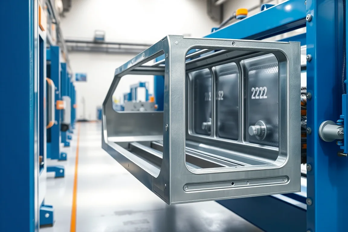
What an EV battery tray frame actually is
An EV battery tray frame is not a simple rectangular tube. It is the load-bearing and locating structure that surrounds, supports and protects the battery enclosure. It usually contains a floor or lower pan, an upper frame or cover flange, and interfaces for module mounting, structural attachment to the vehicle body, sealing, and electrical pass-through. In many designs it is part of the crash load path, so the frame contributes to intrusion resistance as well as to sealing and corrosion performance. That combination makes the frame a safety-critical assembly whose design must be validated as a system, not as a single formed profile.
A roll forming machine for this component is therefore only one manufacturing step in a longer chain. The machine can produce straight or swept frame rails, side members, cross-members and edge profiles, but it cannot by itself create a qualified battery enclosure. Understanding that boundary is the first step in specifying the right equipment.
Profile geometry and the interfaces that drive tooling
The starting point is the controlled part drawing. For a battery tray frame, the drawing typically defines the section shape, the datum scheme, hole patterns, joining flanges, sealing surfaces, and the interfaces to the floor pan or cover. Each of these elements affects how the profile must be formed and how it is later assembled.
Sealing surfaces need flatness and surface integrity; they mate with gaskets, adhesives or compression seals. Joining flanges are the edges where the frame is welded, riveted, clinched or bonded to adjacent parts, so their angle, length and edge condition matter. Mounting interfaces and fastener holes must be positioned relative to the datums used in the vehicle body. If the roll formed profile carries holes, the piercing operation must hold position relative to the same datum scheme, otherwise assembly fixtures will fight the part.
Because battery tray frames often include bends in more than one plane, the tooling may need to form both the cross-section and a sweep or longitudinal curvature. That is a different level of complexity from a straight automotive profile, and it should be discussed explicitly when defining the pass schedule and the cutoff.
Material choice and why it changes the forming strategy
The material is usually drawing-specified automotive steel or another validated alloy. The grade, strength, coating and allowable variation all influence roll forming. Higher-strength steels tend to exhibit more springback, may require larger bend radii and different pass development, and can be more sensitive to edge cracking. Coatings such as zinc-based finishes affect friction, tooling wear and the need to protect the coating during forming and cutoff.
The buyer should specify base-metal thickness and grade, plus the allowable range that the line must handle. That range requires supplier verification; a machine that forms one thickness well does not automatically form a family of thicknesses with equal quality. The material also drives whether lubricant is needed, what roll material and surface treatment are appropriate, and how much forming force the stands must develop.
How roll forming compares with competing production routes
Roll forming is one candidate route for battery tray frame elements, but it competes with press brake forming, stamping, extrusion and hybrid approaches. Each has different economics and different fit with the part.
- Roll forming suits long, relatively constant cross-sections produced in volume. It can integrate piercing, notching and cutoff, giving good dimensional repeatability along the length and low per-part labor. It is less flexible for large changes in width or for deep drawn features, and tooling development is a significant upfront commitment.
- Press brake forming is flexible and has lower tooling cost, which can suit low volumes or early prototypes. It is generally slower for high-volume production and holding long, repeatable bends on a large frame can be more variable.
- Stamping can produce complex three-dimensional shapes and integrated features, but the dies are expensive and the process is usually limited to shorter parts unless very large presses are used.
- Extrusion can create constant aluminum cross-sections efficiently, but it does not produce the steel flanges and joining details common in steel frames without secondary machining.
The correct route depends on volume, length, cross-section complexity, material, and how much secondary joining is acceptable. A roll forming line is most attractive when the frame can be built from one or more constant-section profiles joined at corners or to cross-members.
From coil to formed profile: what the line does
A typical process sequence for an EV battery tray frame roll forming machine is: traceable coil feed, precision forming, feature and cut operations, joining, and dimensional verification. The machine scope often ends after forming and cutting, with joining handled in a separate cell or fixture. That distinction matters because the frame's final geometry may be defined after welding or bonding, not by the formed profile alone.
Coil feed should be traceable so that material grade, heat or lot can be linked to the parts produced. Precision forming is carried out in a series of roll stands, each making an incremental bend. Feature operations can include piercing holes, notching, embossing, or forming locating features. Cutoff then separates the part. The cutoff must be profile-supported, meaning the tooling and the machine structure support the section during the cut so the end is not crushed, twisted or distorted. Cut length, end squareness and burr condition should be defined because they affect downstream assembly.
If the frame needs a sweep or a curved shape, the line may include a sweep unit or a post-forming operation. This is a substantial scope item and should not be assumed.
Assembly, joining and the boundary with part validation
When the formed pieces leave the line, they become a frame through joining. That joining can be welding, adhesive bonding, riveting, clinching, bolting or a combination. Each method has its own fixture, access and quality requirements. For example, welding near a sealing surface may distort the flange and require post-weld correction; adhesive bonding requires controlled gap and surface preparation; self-piercing rivets need access on both sides.
The roll forming machine supplier typically provides forming and cutting hardware, but the assembly process, joining parameters and final validation are usually the responsibility of the battery enclosure integrator or OEM. It is important to separate production hardware from part-validation responsibilities in the quotation and project plan. The machine can be qualified for forming and cutting; the finished frame is qualified as an assembly, including sealing, crash and environmental performance.
Inspection and acceptance: what to measure and when
Inspection should begin with the datum scheme. The drawing defines which surfaces and features are the datums for measurement. The formed profile, the pierced holes, the cutoff ends and the final assembly should all be measured relative to those datums. Using a different reference can make good parts look bad or mask real variation.
Acceptance criteria should be agreed before tooling approval. That includes tolerances on section dimensions, bend angles, hole positions, cut length, end quality and surface condition. For safety-critical frames, the OEM may also require material certificates, traceability records and process capability evidence. The measurement method, gauge and frequency should be defined so that both the machine builder and the buyer are working to the same standard.
First-off pieces from the actual material and profile should be inspected, followed by a representative steady-production sample. A demonstration using a different, easier material does not prove the line can hold the drawing tolerances on production material.
Production targets, scrap and changeover
Output for an EV battery tray frame line should be defined as accepted parts per shift with the actual profile and material, not as a no-load speed. Cycle time should include feeding, forming, piercing, cutoff, unloading and any in-line inspection. Setup scrap and changeover time are often underestimated; if the line must run more than one frame variant, the changeover procedure and its scrap should be recorded and included in planning.
Output also depends on material yield and on how many secondary operations are moved off the line. If a part must be deburred, cleaned or joined after cutoff, those steps affect the real capacity of the cell.
Electrical supply and installed power
The buyer should state the plant voltage, frequency and phase. Installed power must be confirmed from a complete equipment schedule that includes drives, pumps, controls, heating or welding equipment, and any auxiliary units. A machine's nameplate alone may not represent the actual connected load. This is a site-planning matter that should be resolved before equipment layout is finalized.
Practical checklist before approving a production line
- Confirm the part drawing, datum scheme and all interfaces are released and consistent.
- Specify material grade, thickness range, coating and allowable variation.
- Review forming simulation or trial evidence for the actual material and section.
- Confirm access for piercing, notching, welding or sweeping operations.
- Agree cutoff method, end quality and cut length tolerance.
- Separate forming and cutting scope from joining and validation scope.
- Define inspection method, gauges and acceptance criteria before tooling approval.
- Run the agreed material and profile, not a substitute.
- Inspect first-off and steady-production samples with the agreed gauges.
- Record changeover steps, setup scrap, punching time and unloading time.
- Compare the written equipment scope with all secondary operations needed for a finished part.
- Confirm electrical supply and installed power from a full equipment schedule.
FAQ: EV battery tray frame roll forming
Can a roll forming machine produce a complete battery tray frame?
No. Roll forming can produce the straight or swept rails, side members and cross-members that make up the frame, but the frame is completed by joining those pieces, often with welding, bonding or riveting, and by adding the floor pan or cover. Sealing, crash performance and environmental durability are properties of the assembled and validated enclosure, not of the formed profile alone.
Why is the datum scheme so important for this component?
The datum scheme ties the formed profile, the holes and the final assembly to the vehicle body and to the battery modules. If the roll forming line uses a different reference than the assembly fixture, parts that measure well in isolation may not fit or may create sealing gaps. Datums should be defined on the drawing and used consistently for tooling design, inspection and assembly.
What material information should be provided to the machine builder?
The drawing-specified grade, base-metal thickness and coating, plus the allowable range the line must handle. High-strength steels and coated materials can require different bend radii, springback compensation and tooling surfaces. Without verified material data, the builder cannot confirm forming feasibility or pass development.
How does roll forming compare with stamping for battery tray frames?
Stamping can create complex three-dimensional shapes and integrate features, but die cost is high and part length is limited. Roll forming is efficient for long, constant cross-sections and can integrate piercing and cutoff, but it is less suited to deep drawn details. The choice depends on volume, length, geometry and whether the frame can be built from joined constant-section profiles.
What should be inspected on first-off parts?
All features called out on the drawing that are produced by the line: section dimensions, bend angles, hole positions, cut length, end squareness and surface condition. Measurements should be taken relative to the agreed datums, using the agreed gauge and method. First-off inspection should be repeated on a steady-production sample to confirm the process holds over time.
Does roll forming guarantee the crash performance of the battery enclosure?
No. Crash performance is a system-level property that depends on the frame design, material, joining, the floor pan or cover, and the vehicle integration. Roll forming can produce the frame members to drawing, but crash, sealing and environmental requirements must be validated on the defined assembly.
Quotation scope and what to clarify
A quotation for an EV battery tray frame roll forming machine should state what is included and what is excluded. Tool development, trials, gauges, joining equipment, qualification support and operator training can be substantial scope items. It should also state the assumed material, profile, thickness, cut length and output definition. If any of these are left vague, the price is not comparable to another offer. Buyers should ask for a written equipment schedule, a process sequence, and a clear division between machine acceptance and part validation.
Separating forming from assembly and validation
Roll forming is a candidate manufacturing step for EV battery tray frame members. It can deliver repeatable, long profiles with integrated features, and it can be part of a cost-effective route when the frame is designed around constant-section profiles. But the machine does not certify the part. The path to a qualified battery tray frame runs through a validated design, agreed datums and acceptance criteria, verified material behavior, controlled joining, and inspection at the assembly level. Keeping those responsibilities distinct helps ensure that the equipment specification, the quotation and the validation plan all match the actual component.

Continue your research
- Automotive Roll Forming Machines
- Automotive Bumper Beam Roll Forming Machine
- Automotive Door Beam Roll Forming Machine
- Automotive Seat Rail Roll Forming Machine
- Automotive Window Guide Channel Roll Forming Machine
- Heavy Truck Side Member Roll Forming Machine
- How Automotive roll forming machine Works
- How To Choose a Automotive roll forming machine
- Automotive roll forming machine Price: What Affects the Cost?
Configuration & specification inputs
Match the configuration to your section drawing, material and production requirements.
| Parameter | Requirement / confirmation needed |
|---|---|
| Profile geometry | An EV battery-tray frame is part of a safety-critical enclosure. Material joining, sealing, crash and corrosion requirements require a validated design; roll forming is only a candidate manufacturing step. |
| Material | Drawing-specified automotive steel or other validated alloy |
| Thickness & grade | Buyer to specify base-metal thickness and grade; operating range requires supplier verification. |
| Process route | Traceable coil feed → precision forming → feature/cut operations → joining → dimensional verification |
| Cutting | Confirm profile-supported cutoff, cut lengths, end quality and any secondary operations. |
| Output | Define accepted output per shift with the actual profile and material. |
| Electrical supply | Buyer to state voltage / frequency / phase. Installed power requires a confirmed equipment schedule. |
| Acceptance | List corner assembly, machining or piercing, joining and inspection where specified. Check datums after the complete process. Battery enclosure sealing, crash and environmental performance need validation of the defined assembly. |