
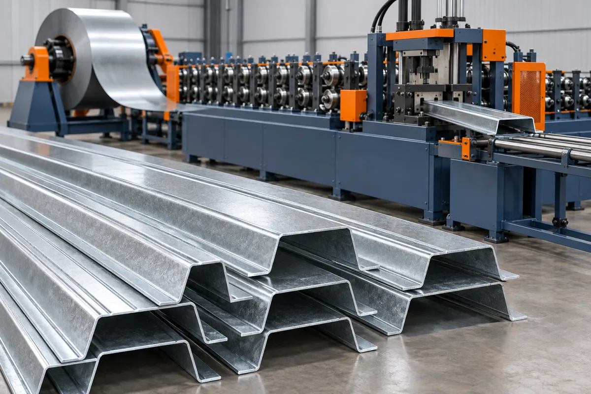
An omega purlin roll forming machine produces a hat-like support section whose raised central portion connects to outward-facing feet or flanges. The exact shape varies by system, so omega should be treated as a section family rather than a universal drawing. Crown width, depth, feet and any returns determine both forming and the intended connection.
The profile differs from an open C or Z purlin because its support and fixing surfaces are arranged around the raised crown and outward feet. That changes the tooling sequence, hole references and mating interfaces. A buyer should begin with the full section and assembly rather than a familiar symbol.
Which omega dimensions define the member?
Show crown width, overall depth, sidewall angles, foot widths and bend radii. Identify any lips, returns or asymmetric details. State whether the section is intended to be symmetric and which surfaces establish the inspection datum.
Include overall width and developed strip requirements separately. The raised geometry consumes material that is not visible in the projected width. Coil purchasing should follow the approved developed section rather than a simple outside measurement.
How does the section interface with the structure?
Provide drawings of the contact and fastening surfaces. Some systems use the outward feet as mounting areas, while the crown supports another component; the actual design must establish the relationship. Include brackets or mating parts where they control fit.
Do not transfer a connection detail from a ceiling hat channel or another visually similar product without review. An omega purlin is defined by its intended structural system, material and geometry, not merely by resemblance to a smaller profile.
What should the feature schedule contain?
Identify holes or slots in the crown, sidewalls or feet and define them from finished-section datums. State the pattern along the member and its relationship to cut ends. Tool access and feature sequence depend on where those features are located.
- Feature sizes and shapes.
- Transverse positions on each relevant surface.
- Longitudinal spacing and end distances.
- Required solid zones and special ends.
- Member orientation and identification.
Use actual mating references in the trial. A correct overall section can still be difficult to assemble if holes were specified from inconsistent surfaces.
How is the hat-like shape formed?
Controlled entry feeds the strip through progressive stages that develop the crown, sidewalls and outward feet. The planned sequence must preserve access for tools as the section rises. Any edge returns and feature-making operations need a defined place in the route.
After forming, the cutting system separates the member and the takeoff supports the full section. Review how the crown and feet are supported near cutoff. Local deformation in either area can affect the final mounting interface.
How should material combinations be selected?
Specify grade, base-metal thickness and coating for each target section. The same outside shape in a different material is a different forming case. Pair dimensions and material rather than listing independent maximum values.
During trials, inspect bends and surface condition and retain coil identification. If the line will serve several omega variants, choose representative cases covering normal production and the demanding combinations in the proposed matrix.
Can the crown and foot widths vary?
Only within the engineered tooling arrangement. A change to crown width can affect sidewall position, foot spacing and the developed strip requirement. A foot-width change may also alter punching references or cutting support.
Ask for a configuration matrix explaining adjustments and replacement parts. Demonstrate a change through a measured member and a successful mating-interface check. This is more informative than showing that the roll stands can move.
Which shape checks are most useful?
Measure crown width and height, foot positions, sidewall angles and any returns. Check whether the intended contact surfaces lie in the required relationship without forcing the member onto a fixture. Assess straightness and twist on agreed supports.
Inspect the ends separately for flare or local crushing. Compare the member before and after normal stacking because narrow feet or returns can be affected by packaging pressure. The accepted geometry should survive the actual handling route.
How should the full production trial be organized?
- Confirm section and connection drawings.
- Run production-intent material and feature patterns.
- Measure crown, sidewalls, feet and holes.
- Inspect straightness, twist and cut ends.
- Check the mounting and supported-component interfaces.
- Demonstrate size changes and bundle handling.
- Record accepted members and rejected-start causes.
Compare output using the actual length and hole mix. A line making long unpunched sections has a different cycle from one making short members with several mounting patterns.
Frequently asked questions
Is an omega purlin the same as a hat furring channel?
They can look similar, but their dimensions, material and intended systems may differ. Use the actual purlin drawing and connection requirements rather than transferring assumptions from another product.
Must the two feet be identical?
Follow the specified section. Symmetry should be shown explicitly; special products may use different widths, holes or returns on each side.
Can holes be punched after forming?
That depends on feature access and the proposed equipment. Ask the supplier to explain the sequence and demonstrate the final positions using the actual section.
Why inspect the contact surfaces without force?
A fixture can conceal an incorrect relationship between the crown and feet. The agreed inspection method should represent the member's delivered shape before installation restraints are applied.
What should a quotation request include?
Provide the complete omega section, material matrix, connection features, lengths and mating parts. Add required variants and bundle format to define the full forming and handling scope.
Specify the crown and feet as one interface
An omega-purlin project succeeds when its raised section and mounting surfaces are controlled together. That definition guides tooling, feature registration and acceptance toward the actual support member rather than a generic hat shape.

Continue your research
- Purlin Roll Forming Machines
- C Purlin Roll Forming Machine
- Z Purlin Roll Forming Machine
- 80-300mm CZ Purlin Roll Forming Machine
- 100-400mm CZ Purlin Roll Forming Machine
- Automatic Size Change CZ Purlin Machine
- How Purlin roll forming machine Works
- How To Choose a Purlin roll forming machine
- Purlin roll forming machine Price: What Affects the Cost?
Configuration & specification inputs
Match the configuration to your section drawing, material and production requirements.
| Parameter | Requirement / confirmation needed |
|---|---|
| Profile geometry | Approved omega crown, depth, sidewalls, outward feet and any asymmetric returns. |
| Material | Specified purlin steel grade and coating for the complete hat-like support section. |
| Thickness & grade | Material-thickness combinations reviewed with crown, feet and developed strip requirements. |
| Process route | Guided entry, defined punching, progressive crown and foot forming, supported cutting and stacking. |
| Cutting | Lengths with undistorted crown and mounting feet at the cut ends. |
| Output | Accepted omega members for the stated feature pattern, size changes and bundle format. |
| Electrical supply | Site utilities matched to the selected forming, feature and handling arrangement. |
| Acceptance | Crown and foot geometry, contact relationships, holes, straightness, twist and mating interfaces. |