
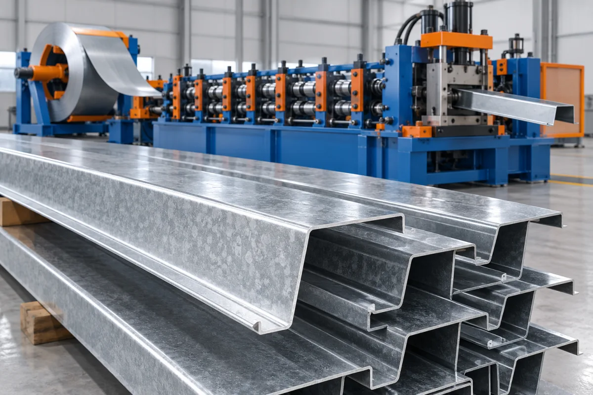
A Z purlin roll forming machine produces steel members with principal flanges extending to opposite sides of the web. The section orientation, flange dimensions, lips and connection features define the finished component. For a business supplying several Z sizes or connection patterns, the key equipment question is how reliably the line reproduces that complete member after each setup change.
Z-shaped geometry is not just a C channel described differently. The opposed flanges affect drawing interpretation, tooling and inspection references. Where a design uses overlapping members, the mating arrangement adds another practical check that cannot be replaced by measuring web depth alone.
What is the finished product specification?
The production target is the approved Z section, cut to length and supplied with the required holes, slots or other features. Establish whether all those features are made in-line or whether another operation is needed. A plain formed section and a finished connection-ready member should not be treated as equivalent outputs.
Identify the section orientation on the drawing and order schedule. A mirrored view can create ambiguity if hole locations or unequal dimensions are interpreted from the wrong side. Keep the definition consistent through tooling, programming, marking and inspection.
Which Z-section variants need separate attention?
A fixed section with multiple cut lengths
The main variation may be length and the longitudinal hole program. The forming setup can remain focused on one geometry, but the order data and feature references still need to produce the correct finished members.
A family of web and flange sizes
List the complete combinations rather than a collection of independent ranges. Determine which transitions need adjustments and which need tools or supports changed. A web-depth range does not automatically include every lip or flange arrangement.
Members used in a specified overlap assembly
Provide the mating arrangement, associated hole pattern and any dimensional relationship required by the design. Do not assume all similarly named Z sections overlap in the same way. Approve the relevant pair or connection, not only one isolated sample.
How should orientation and hole datums be documented?
Show the section with clearly identified faces, flange directions and measurement references. State how the part is viewed when describing left and right features or hole positions. This is especially useful when similar lengths have different end patterns.
- Web, flange and lip dimensions with specified bend radii.
- Section orientation and any unequal features.
- Hole and slot locations relative to controlled datums.
- The relationship of each end pattern to finished length.
- Required identification for members that look similar.
- The mating components or overlap arrangement used for approval.
Use one approved reference through the complete process. An otherwise accurate line can produce the wrong part if an order program interprets the drawing from a different direction than the inspection team.
How does a Z purlin production route work?
- Prepare the coil: verify material and establish loading, strip guidance and any required preparation.
- Make connection features: produce holes, slots or notches at the stage defined by the proposed route.
- Form the section: progressively develop the opposed flanges and any returns.
- Control and cut length: maintain the required relationship between the features and finished ends.
- Discharge and identify: support members and preserve the order reference.
- Inspect and assemble: measure the section and check the specified connection or overlap.
Ask the supplier to explain the actual operation sequence and how the section is supported at each transition. Punching before or after forming changes the tooling and access questions; the right assessment is against the required component, not an assumed universal layout.
What makes punching a complete requirement?
Specify more than hole diameter. Feature shape, material, quantity, position and end reference affect the production task. Include any special slots or notches and identify which must align in an assembled connection.
For multiple section sizes, clarify how punch positions change and which dies or supports are required. Automated forming adjustment does not necessarily adjust every feature operation. The changeover description should cover these items and the first-off checks needed afterward.
Use a finished sample to verify the program's interpretation. A hole can be correctly punched but referenced to the wrong end or face. Comparing the member with the actual mating arrangement makes that kind of mistake visible.
How should size changes and C/Z switching be compared?
Changing dimensions within a Z family is different from switching to a C section. A dedicated Z line may cover the required size matrix without providing another section orientation. A combined line needs its own specified tooling and changeover method.
Ask for a transition schedule that identifies adjustments, replacement tools, guides, punch work and cutting support for each change. Measure recovery through to an accepted part with the correct hole program. Timing only the movement of forming components gives an incomplete picture.
If orders require frequent returns to earlier sizes, demonstrate that repeatability. Retain setup references against the actual drawing and material so a nominal size name does not conceal a changed lip or connection pattern.
Why do material combinations need a matrix?
Thickness, strength, strip width and section geometry together determine the task. A list of separate maximum values should not be interpreted as permission to combine all of them. Review the intended combinations with the equipment supplier and identify those that need demonstration.
Specify coating and any later processing in the component route. Use representative material in trials and keep its identity with the dimensional records. This provides a basis for investigating springback, shape or finish changes without attributing every difference to the same cause.
The structural design establishes which material the finished member requires. Substituting another grade because it forms easily does not prove that the resulting Z section can serve the same purpose.
What should overlap and connection inspection look like?
Where the design calls for overlapping or connected Z members, supply the relevant component drawings and assemble representative samples. Check whether holes align as intended and whether the members meet without unplanned local modification.
Keep the support and measurement conditions defined. A long member may look different when restrained or unsupported, so straightness and twist should be judged by the agreed method. Measure after cutoff as well as where needed earlier in the process to identify the stage introducing a deviation.
Do not use assembly force or enlarged holes to hide a manufacturing error during approval. Record the deviation and address its cause within the controlled drawing and production process.
What drives cost and usable output?
The complete size matrix, feature programs and material range explain more than the generic Z-machine label. Quotation scope should include required tooling, coil handling, punching, cutting, discharge and identification. Separate installation and inspection responsibilities from the hardware total.
For output, count accepted members over the agreed order mix. Dense hole programs, short lengths, changes in size and unloading can all influence delivery. Keep rejected starts and setup material visible rather than reporting only uninterrupted strip speed.
Compare a dedicated Z arrangement with a combined C/Z line using the same schedule. One shared line may offer useful flexibility while also concentrating different orders on one production resource. Assess that tradeoff against actual delivery needs.
What should the trial prove before acceptance?
- Confirm orientation, drawing revision, material and feature program.
- Measure the complete section, including opposed flanges and lips.
- Check hole datums and both finished ends.
- Assess agreed straightness and twist after normal discharge.
- Assemble the required connection or overlap where applicable.
- Demonstrate a meaningful size change and return setting.
- Verify identification, stacking and accepted-output records.
A successful trial should show the actual connection-ready product. Structural capacity and installation requirements remain part of the designed system and cannot be inferred from a machine's adjustment range.
Frequently asked questions
Is a Z section just a reversed C section?
The principal flange arrangement differs, and the tooling and inspection requirements must follow the actual drawing. A line needs the stated capability to produce the required section; changing its description or feed orientation is not a substitute.
Do all Z purlins overlap interchangeably?
No. Compatibility depends on the specified sections and connection design. Supply the mating arrangement and relevant hole details. A shared nominal web depth is not enough to establish fit.
Can one machine make every Z size?
Only the agreed configuration envelope is relevant. Web, flange, lip, material and feature combinations need review. Ask which variations are adjustable and which require additional parts rather than assuming an unlimited range.
How should left and right hole patterns be described?
Use the drawing's defined orientation and datums, with a clear viewing direction and end reference. Carry that convention through the order program and inspection. Avoid relying on an operator's informal interpretation of a sketch.
Does a combined C/Z line have no manual changeover work?
That depends on the actual design and supplied tooling. Punches, supports, guides or inspection may still require intervention. Evaluate the full transition through to an accepted member with the correct features.
What should be included in an enquiry?
Provide the section matrix, material combinations, connection drawings, lengths and order pattern. Add the required overlap samples or mating components. These inputs support a meaningful comparison of tooling, changeover and output.
Keep the Z geometry and its connection references together
A complete specification connects opposed-flange geometry with orientation, features and assembly. Use those references to evaluate the line at the extremes of the required production mix. This turns a general Z-purlin request into a repeatable manufacturing target rather than an ambiguous size range.

Continue your research
- Purlin Roll Forming Machines
- C Purlin Roll Forming Machine
- CZ Purlin Roll Forming Machine
- 80-300mm CZ Purlin Roll Forming Machine
- 100-400mm CZ Purlin Roll Forming Machine
- Automatic Size Change CZ Purlin Machine
- How Purlin roll forming machine Works
- How To Choose a Purlin roll forming machine
- Purlin roll forming machine Price: What Affects the Cost?
Configuration & specification inputs
Match the configuration to your section drawing, material and production requirements.
| Parameter | Requirement / confirmation needed |
|---|---|
| Profile geometry | A Z purlin places its flanges on opposite sides of the web. Show the installation and lap orientation on the drawing so punching and cutoff are not inadvertently mirrored. |
| Material | Specified galvanized or uncoated structural steel grade |
| Thickness & grade | Buyer to specify base-metal thickness and grade; operating range requires supplier verification. |
| Process route | Payoff → leveling → punching/notching → adjustable forming → cutoff → dimensional inspection |
| Cutting | Confirm profile-supported cutoff, cut lengths, end quality and any secondary operations. |
| Output | Define accepted output per shift with the actual profile and material. |
| Electrical supply | Buyer to state voltage / frequency / phase. Installed power requires a confirmed equipment schedule. |
| Acceptance | For a Z-only former, establish the supported size matrix and tool changes. For a combined line, add a complete C-to-Z demonstration. Distinguish flange and lip changes from web-depth adjustment, and include the cutoff and punch setup in the comparison. |