
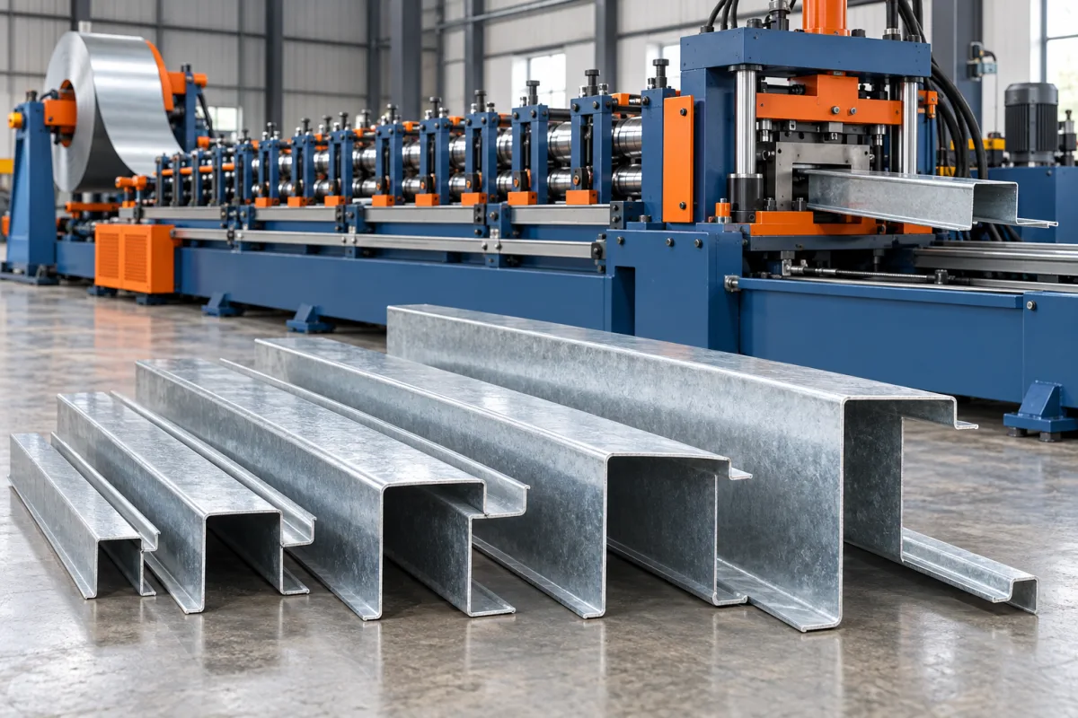
An 80–300 mm CZ purlin roll forming machine enquiry describes a desired purlin family, usually by its nominal web-depth range. The numbers should be treated as a project requirement to confirm against a detailed size matrix, not as a complete equipment specification. Flanges, lips, thickness, material strength and hole patterns must be reviewed alongside web depth.
The main value of a combined CZ route is the ability to serve C and Z section orders using an agreed change arrangement. The practical result depends on how quickly the line recovers the correct section, punching positions and cut ends across the intended range.
What should the 80–300 mm range describe?
State whether the dimension is nominal web depth and identify the measurement convention. List the actual sizes needed rather than assuming every intermediate dimension is required. Add flange and lip dimensions for each size, including any asymmetry in the Z section.
The smallest and largest web depths may create different forming and handling conditions. They should both appear in the review, but so should difficult combinations of flange, lip, thickness and grade within the range.
How do C and Z profiles differ?
A C section has its flanges on the same side of the web, while a Z section places them on opposite sides. Their lips and flange proportions follow the selected structural-product drawings. A combined line must reproduce both geometries using its specified conversion method.
Where Z members are intended to lap or nest, provide the complete mating detail. Do not assume equal flange dimensions or a generic Z sketch will satisfy the required assembly. The manufacturing reference should follow the actual purlin system.
Which inputs belong in the size matrix?
- Web depth, flange widths and lip dimensions.
- Material grade and base-metal thickness for each section.
- Input strip width and coil envelope.
- Hole sizes, patterns and reference datums.
- Member lengths and end conditions.
- Required C-to-Z and size-change sequences.
A matrix exposes combinations that a simple range statement hides. It also gives suppliers a common basis for identifying which dimensions adjust automatically, which need manual work and which require different tools.
How does the production route work?
Coil handling and entry preparation feed strip into the specified punching and forming sequence. The rolls develop the web, flanges and lips into the chosen C or Z shape. The cutting arrangement produces member lengths, followed by supported discharge and identification.
Ask where punching and cutting occur relative to forming. The proposed sequence affects feature access, end condition and production cycle. Its suitability should be demonstrated with actual hole patterns and short as well as long members.
What does an automatic size change include?
Automation may adjust some section dimensions while leaving other tasks manual. Coil changes, punch tools, guides, cutoff components and inspection can still be required. Ask for an operation-by-operation description instead of accepting automatic as a complete changeover specification.
Time the transition from the last accepted old member to the first accepted new member. Include hole-position checks and any startup rejects. This measures the scheduling benefit the business will actually receive.
How should punching be registered?
Define hole positions from clear longitudinal and transverse datums. Identify the relevant web or flange surfaces and account for the final formed section. A flat-strip hole location is not always the most useful way to specify the finished member.
Trial representative connection patterns with the intended mating references. Check edge distances and cut-to-hole relationships against the approved drawings. The line should not be approved from unpunched samples if punched purlins are the normal saleable product.
What should be checked across the range?
Measure web, flanges, lips, angles, straightness and twist using agreed supports and methods. Inspect end flare or local distortion near cutoff. Material identification matters because section behavior can change with grade and thickness.
Choose trial combinations that represent the practical limits and normal production, not only a convenient middle size. Include a C-to-Z conversion and at least one size change that affects punching or cutting setup.
How should output and quotation scope be compared?
Use accepted members from a defined order schedule. Hole count, pattern changes, cutting and discharge can determine output even when the forming mill runs quickly between features. Include the agreed handling and labeling requirements.
- Confirm the full size and material matrix.
- Identify all C/Z conversion and size-change tasks.
- List punch and cutoff tools for required variants.
- Demonstrate representative members and connections.
- Record accepted output, changeover time and startup scrap.
- Retain dimensional and material records for each approved sample.
Structural member design remains a separate responsibility. Producing a purlin accurately does not determine its allowable span or loading without the relevant system design.
Frequently asked questions
Does 80–300 mm include every flange and thickness?
No. A web-depth range does not define all combinations. Provide a size matrix with flanges, lips, material grade and thickness so the proposed equipment envelope can be reviewed.
Can C and Z use the same punching programs?
Only where the finished-member drawings support the same references and patterns. Verify feature positions after conversion instead of assuming the geometry change leaves every datum unchanged.
Does automatic change mean no tool changes?
Not necessarily. Some dimensions may adjust while punch or cutoff tools still change. Ask for the complete sequence and time it through the first accepted member.
Why test the smallest web size?
It may create different tool-clearance, flange or handling conditions from larger members. The entire required range should be represented by suitable trial combinations.
What is the best starting document?
A controlled C/Z section matrix with material combinations, hole drawings and member lengths. Add the expected order mix and desired conversion sequence to support a realistic equipment comparison.
Turn the range into a production matrix
The 80–300 mm description becomes useful when every required section is connected to its material, holes and changeover method. That is the basis for a combined CZ line that serves actual orders rather than only a nominal dimensional range.

Continue your research
- Purlin Roll Forming Machines
- C Purlin Roll Forming Machine
- Z Purlin Roll Forming Machine
- 100-400mm CZ Purlin Roll Forming Machine
- Automatic Size Change CZ Purlin Machine
- Quick Change C Purlin Roll Forming Machine
- How Purlin roll forming machine Works
- How To Choose a Purlin roll forming machine
- Purlin roll forming machine Price: What Affects the Cost?
Configuration & specification inputs
Match the configuration to your section drawing, material and production requirements.
| Parameter | Requirement / confirmation needed |
|---|---|
| Profile geometry | Requested 80–300 mm nominal web-depth family with independently specified C/Z flanges and lips. |
| Material | Purlin steel grades paired with each intended section and coating requirement. |
| Thickness & grade | Per-section base-metal thickness and strength combinations reviewed across the requested range. |
| Process route | Coil preparation, registered punching, C/Z forming, length cutting and member identification. |
| Cutting | Required member lengths with controlled flare, end quality and hole-to-end registration. |
| Output | Accepted punched members for the agreed size mix, C/Z conversions and handling conditions. |
| Electrical supply | Site supply and utilities for coil handling, punching, forming, cutting and discharge. |
| Acceptance | Web, flange, lip, angle, straightness, twist, connection features and recovery after size changes. |