
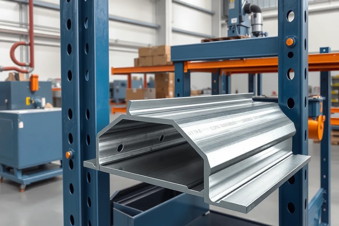
A teardrop rack upright roll forming machine makes the specified perforated upright section for a pallet-rack system using teardrop-style beam connections. The slot pattern and the formed column must work together with the intended beam-end connector. A familiar hole shape alone does not make uprights from different systems interchangeable.
The machine specification should begin with the complete upright and connection drawings. It must address slot geometry, pitch, section shape, material, bracing interfaces and finished-part identity. The trial should demonstrate an actual rack connection rather than only a straight perforated profile.
What defines the teardrop connection?
Show the slot outline, orientation and location on the upright face. Include the mating beam-end connector and any locking or retention component required by the system. The relevant dimensions are the ones that establish normal engagement and seating.
Do not use the phrase universal teardrop as a substitute for compatibility review. Similar openings can differ in size, spacing, material or the surrounding section. Use the actual intended parts during acceptance.
Which upright section details matter?
Define the front face, sidewalls, returns, depth and radii. Identify the surfaces used for beam connections and frame bracing. The slot locations should be tied to these finished-section datums.
- Front-face width and slot rows.
- Upright depth and side-return geometry.
- Bracing holes or attachment details.
- Base or end interfaces.
- Material, coating and product identity.
A correct front face is not enough if the side geometry prevents frame assembly. Review the complete upright component and the operations that turn it into a rack frame.
How should slots be registered to length?
Define pitch, reference end and any required unperforated zones. The relationship between the first slot and the finished end can affect beam levels and frame assembly. The machine program should reproduce the approved pattern for every ordered length.
Trial different lengths and inspect the final slots near each end. A repeat pattern that works in the middle of a long sample may not establish correct end margins or base-interface clearance.
How is the upright manufactured?
The route prepares strip, creates the specified openings and progressively forms the column section. Depending on the proposed process, cutting and feature operations may occur at different stages. The supplier should explain the sequence for the actual upright.
Downstream frame bracing, base attachment, coating and other assembly operations should be identified separately. A roll-formed upright is not automatically a complete rack frame, and the quotation should make that boundary clear.
What material and feature quality should be checked?
Pair steel grade and base-metal thickness with each upright section. Include the coating route and final connection condition. Slot quality should be assessed using the actual material, not only an easy trial strip.
Inspect the slot outline, edge condition and nearby face distortion. Also measure the section after forming because the relationship between openings and connector surfaces matters in the final component. Retain material identity with the approval sample.
Can several upright sizes share one line?
A wider face, deeper section or different return may require tool changes beyond the slot program. Ask for a matrix covering rolls, punches, guides and cutoff parts. A shared teardrop pattern does not imply shared forming geometry.
Demonstrate first-good-upright recovery after a meaningful change. Include a beam-connector fit check and the relevant bracing interface. This shows whether the full rack component, not only its width, has been recovered.
How should long uprights be handled?
Use suitable supports for straightness and twist inspection. Check local deformation near cutoff separately. Long uprights should retain their front-face and return geometry through transfer and bundling.
Protect slot edges and preserve component identity during coating and handling. Similar upright sizes may have different material or slot schedules. Bundle labels should make those distinctions clear to frame assembly.
How should slot-tool condition be recorded?
Retain an approved feature sample and the inspection method for its outline and edge condition. Compare production openings with that reference under the equipment supplier's maintenance procedure. A recurring change in connector fit should trigger investigation of the full punching-and-forming route rather than an undocumented adjustment to the beam-end hardware.
What should the rack-connection trial demonstrate?
- Confirm upright, connector and material references.
- Measure section and slot geometry.
- Verify pitch and end registration.
- Engage the intended beam connector and retention component.
- Check bracing and base interfaces within scope.
- Inspect straightness and condition after handling.
- Record accepted uprights and required secondary work.
Rack load capacity and system safety require their own design and qualification. A successful connector fit is a manufacturing check, not a load rating for an arbitrary assembled rack.
Frequently asked questions
Will all teardrop beams fit this upright?
No universal compatibility should be assumed. Compare the exact connector, slot, material and surrounding section, and use the intended components during trials.
Does the machine make complete upright frames?
Only if bracing, joining, base attachment and finishing operations are explicitly included. A formed upright alone is an intermediate component.
Can slot pitch change through a program?
Only within the equipment and approved product scope. The new pattern must remain correctly registered to member ends and the rack-system design.
Why inspect slots after forming?
The connector works with the finished upright face. Forming and handling can affect the relationship between the openings and surrounding geometry.
What should the enquiry include?
Provide the upright and connector drawings, material matrix, slot schedule, bracing and base details, lengths and coating route. Add required variants and expected batch sizes.
Specify the upright and connector together
A teardrop-upright line should be judged by accurate slots in a correct, traceable column section. Connecting those requirements to actual beam and frame interfaces produces a meaningful manufacturing trial.

Continue your research
- Storage Rack & Shelving Roll Forming Machines
- Rack Upright Roll Forming Machine
- Pallet Rack Beam Roll Forming Machine
- Pallet Rack Box Beam Roll Forming Machine
- Pallet Rack Step Beam Roll Forming Machine
- Slotted Angle Roll Forming Machine
- How Storage rack roll forming machine Works
- How To Choose a Storage rack roll forming machine
- Storage rack roll forming machine Price: What Affects the Cost?
Configuration & specification inputs
Match the configuration to your section drawing, material and production requirements.
| Parameter | Requirement / confirmation needed |
|---|---|
| Profile geometry | Controlled rack upright face, depth, returns and teardrop-slot interface with the intended beam connector. |
| Material | Rack-component steel grade and coating route tied to each upright variant. |
| Thickness & grade | Approved thickness and section combinations assessed through punching and forming. |
| Process route | Registered slotting, upright forming, cutting and defined frame-assembly or finishing handoff. |
| Cutting | Upright lengths with correct first-slot reference, end margins and base-interface condition. |
| Output | Accepted identified uprights including slot patterns, size changes and downstream scope. |
| Electrical supply | Utilities for punching, forming, cutoff and selected handling equipment. |
| Acceptance | Slot outline and pitch, formed face, connector and retention fit, bracing references and bundle identity. |