
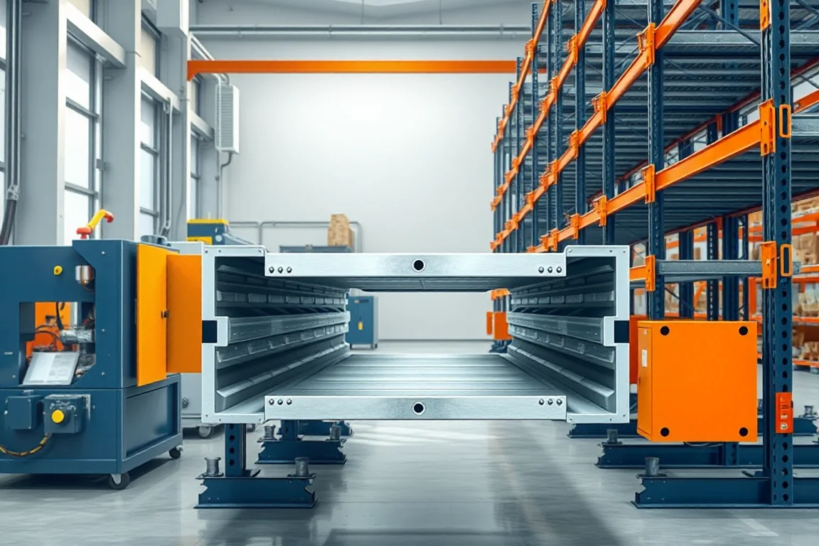
A pallet rack box beam roll forming machine produces the specified closed or assembled box-section beam used in a designed storage-rack system. The production route depends on how that box is constructed: one formed strip with a joined seam, nested formed components or another approved arrangement. The complete beam drawing should decide the process.
The roll-formed section is only part of a saleable rack beam. End connectors, joining quality, length, coating and the interface with uprights or decking all need to be included or clearly assigned to downstream operations. A rectangular outline alone does not establish a complete rack product.
Which box-beam construction is required?
Show the full cross-section, wall thicknesses, radii and seam or overlap arrangement. Identify whether the beam is made from one strip or multiple formed pieces. Include any internal or external joining detail defined by the product design.
Ask the equipment supplier to explain the proposed route for that construction. Do not assume that every box beam can be completed by the same forming mill or that joining is automatically included in a machine-only package.
How does box beam differ from step beam?
A box beam has the specified closed section, while a step beam incorporates a ledge or other geometry intended for a particular support interface. Some manufacturing methods may overlap, but the finished sections and decking relationships differ.
If both products are required, provide separate drawings and connection references. A common overall height does not establish shared rolls, joining fixtures or cutoff support.
Which end-connector details matter?
Provide the connector geometry, attachment method and relationship to the beam ends. The connector establishes how the beam engages the intended upright. Its orientation and position must remain controlled through fabrication.
- Beam length and the reference used to measure it.
- Connector position and handedness.
- Joining and inspection requirements.
- Retention or locking-component interface.
- Finished coating and assembly clearances.
Use actual upright references during acceptance. A beam body with correct dimensions is not enough if its completed end connection does not engage the intended rack.
How should forming and joining be coordinated?
The route develops the required section or component halves, then completes the specified seam or assembly. Joining may be integrated or performed at a separate station. Its location affects handling, dimensional control and the output boundary of the line.
Inspect the completed box after joining rather than approving only open intermediates. The process can affect straightness, squareness and final dimensions. Required joining procedures and quality checks should come from the controlled manufacturing specification.
What material matrix is needed?
Pair steel grade, base-metal thickness and section size. Where more than one component forms the box, identify each material separately. State the coating route and required condition before and after joining.
Trial representative normal and demanding combinations. A section formed successfully in one grade does not establish every other material at the same nominal thickness. Keep material identity with the finished-beam records.
How should length and straightness be checked?
Define whether the ordered length refers to the beam body, connector-to-connector relationship or another system datum. Measure the complete product using that convention. A body cutoff measurement may not establish the final rack span interface.
Inspect straightness and twist after joining and end-connector attachment. Use agreed supports and record local end distortion separately. The finished beam, not an earlier intermediate, is the acceptance target.
Can beam height and width change quickly?
Changes can involve rolls, guides, joining setup, cutoff parts and connector fixtures. Request a matrix for the actual section family. A forming adjustment alone may not recover the complete box-beam process.
Measure changeover through an accepted finished beam and upright fit. Include joining checks, first-piece inspection and startup material. This gives a practical comparison for mixed rack orders.
What should a complete beam trial include?
- Confirm section construction and material identity.
- Measure formed intermediates where useful.
- Complete the specified seam or component joining.
- Attach the intended end connectors within scope.
- Check finished dimensions, straightness and twist.
- Fit the beam to representative uprights and retention components.
- Inspect coating and package condition.
- Record accepted complete beams and downstream work.
Rack capacity requires the complete system's design and verification. A successful fit and accurate box section do not establish a load rating without the appropriate product assessment.
How should finished beams be identified?
Keep section, material, connector and drawing revision linked to each batch. Similar outside dimensions can conceal different wall thicknesses or connector arrangements. Identification should survive normal finishing and packaging.
Check the bundle label against representative finished pieces. This helps prevent an accurately made beam from being delivered under the wrong rack-system specification.
Frequently asked questions
Does the machine weld every box beam automatically?
No. The product construction and equipment scope determine the joining route. Ask which seam or assembly operations are integrated and which remain separate.
Can one strip replace a two-part construction?
That is a product and process redesign, not a simple machine preference. Use the approved beam construction and review any change through the relevant design process.
Are end connectors included?
Only if their manufacture or attachment is explicitly in scope. They are essential to the complete beam and should not be omitted from the overall production plan.
Why measure after connector attachment?
The rack interfaces depend on the completed ends. Body length alone does not establish the final installed relationship or connector alignment.
What should a buyer provide?
Send the box construction, material matrix, joining requirements, end connectors, upright references, lengths and variants. State whether the desired output is a formed body or a completed beam.
Specify the finished box beam, not only its section
A useful rack-beam proposal connects forming to joining and end connections. That makes the equipment boundary clear and gives acceptance a complete, assembly-ready product to verify.

Continue your research
- Storage Rack & Shelving Roll Forming Machines
- Rack Upright Roll Forming Machine
- Pallet Rack Beam Roll Forming Machine
- Teardrop Rack Upright Roll Forming Machine
- Pallet Rack Step Beam Roll Forming Machine
- Slotted Angle Roll Forming Machine
- How Storage rack roll forming machine Works
- How To Choose a Storage rack roll forming machine
- Storage rack roll forming machine Price: What Affects the Cost?
Configuration & specification inputs
Match the configuration to your section drawing, material and production requirements.
| Parameter | Requirement / confirmation needed |
|---|---|
| Profile geometry | Approved closed or assembled box-beam construction with controlled seam and end-connector relationships. |
| Material | Specified steel for each formed component plus the defined coating route. |
| Thickness & grade | Component-specific thickness and grade combinations for the selected box construction. |
| Process route | Section or half forming, specified joining, cutting, end-connector completion and finishing. |
| Cutting | Beam-body and completed-connector length references explicitly defined for the rack system. |
| Output | Accepted complete beams or clearly scoped intermediates with joining and secondary work identified. |
| Electrical supply | Utilities for forming, joining, cutoff, connector fixtures and any included finishing. |
| Acceptance | Completed box geometry, joints, connector position, straightness, upright engagement and final batch identity. |