
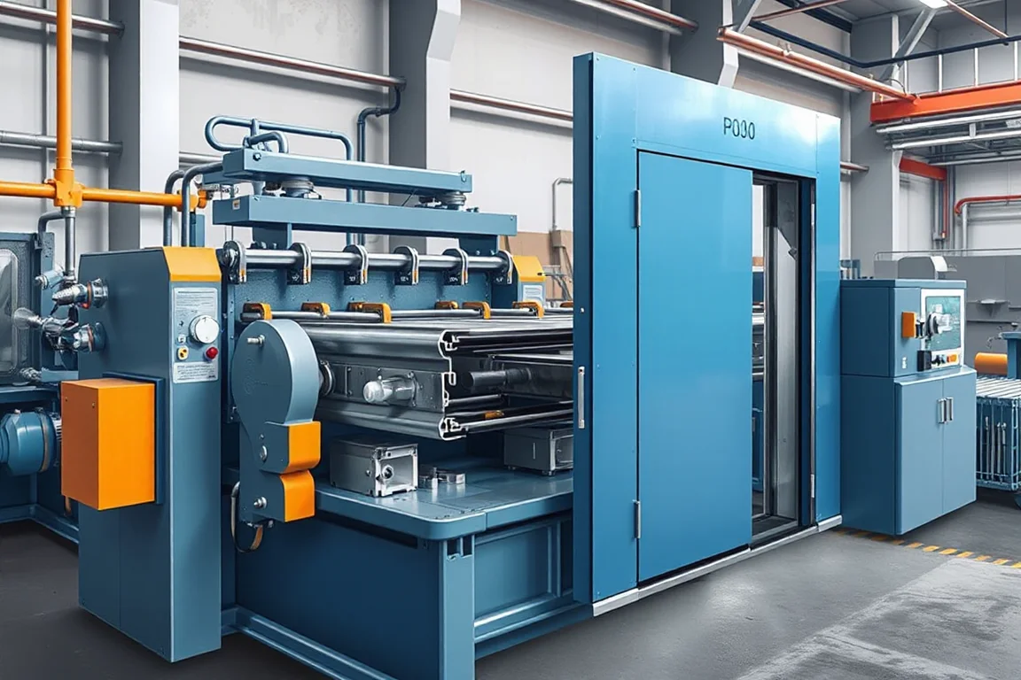
A hollow metal door frame is not a single bent channel. It is a set of jambs and a head whose section usually carries a door rebate, a jamb return or wrap, a stop or seal land, and prepared positions for hinges, strikes, silencers and anchoring. A hollow metal door frame roll forming machine produces that section continuously from sheet steel, but the finished frame only exists after punching, cutoff, corner preparation and joining. This page explains the application, the interfaces between production steps, and how to judge whether continuous forming is the right route for a given frame drawing.
What the formed section actually has to do
The section is the structural and functional interface between the wall opening and the door leaf. The rebate receives the leaf when closed; its depth and face condition influence how the door sits and how the perimeter seal behaves. The return or wrap conceals the rough opening edge and provides a surface for anchor clips or masonry straps. The stop or seal land supports weatherstripping, smoke gaskets or acoustic seals. Hinge and strike preparations are not incidental: they must align across the head and jambs so hardware fits without forcing the frame. Because these features sit on different planes of the same section, the profile must be assessed as a whole rather than as a series of separate bends.
Why the corner detail shapes the production route
Hollow metal frames are typically joined at the corners rather than formed as one continuous rectangle. The standard approaches are welded corners, mechanically joined corners with clips or gussets, and mitered or notched arrangements depending on the frame family. Each choice changes what the roll forming line must deliver. A welded corner needs clean, matching mating surfaces and often a prepared notch or cut. A mechanically joined corner needs specific returns or lips that accept the joining hardware. If the corner strategy is not fixed before the tooling is designed, the formed section may be geometrically correct but impossible to assemble cleanly. That is why a section drawing alone is insufficient; an assembly drawing showing the corner and the hardware preparation belongs in the same package.
Process sequence from coil or blank to joined frame
The typical sequence runs: blank or coil preparation, feature punching, frame forming, cutoff, then corner assembly. Punching may occur before forming while the strip is flat and the tooling has open access, or after forming when hole positions relate to formed planes. Notching for corners and hardware is usually a separate station or a separate machine, and its position in the sequence affects both tool access and hole-to-bend accuracy. Cutoff determines end quality and length consistency, and its design must suit the profile rather than a generic section. Corner assembly, welding, grinding and finishing sit outside the roll former itself. A quotation that covers only the former and not these operations describes an incomplete production route.
Profile features that drive tooling complexity
Narrow returns, deep rebates and close-spaced bends test roll access and the ability to form without marking visible faces. A section with several bends on one side may need more forming stations and careful roll orientation to avoid scuffing the surface that will remain exposed. Features such as a return hem or a seal groove sit close to the main bend, so the tooling must hold those relationships through the whole length. Holes and cutouts introduce additional load and alignment requirements. These are engineering consequences of the drawing, not marketing claims; the practical test is whether a proposed tooling arrangement can produce the complete section consistently.
Material, finish and forming decisions
The material affects both formability and the sequence of operations. The specified sheet steel grade and base-metal thickness determine bending behavior and springback, and they must come from the buyer rather than being assumed. Stainless steel and other alloys behave differently from carbon steel; they usually need separate tooling validation because their work-hardening and springback characteristics change what the rolls and stations must do. Galvanized or coated stock raises questions about coating damage at bends and whether the finish is applied before or after forming. If a protective film is used, the side intended to face outward and the handling of that film through punching and forming should be stated, because surface defects show on the installed frame.
Continuous forming versus other fabrication routes
Continuous roll forming suits frames that repeat with consistent section and length, where the volume justifies dedicated tooling and setup. Press braking suits small batches, unusual sections or frequent design changes, because it avoids tooling commitment but tends to be slower per piece and more variable in bend consistency. A hybrid route, combining formed jambs with fabricated or purchased head sections, can be sensible when one component differs from the rest. The choice is not about which method is better in the abstract; it is about how many frames of that section will be produced, how stable the design is, and whether the corner and hardware preparation can be handled economically alongside the forming operation. Where a design changes often, the cost of re-tooling continuous forming may outweigh its consistency advantage.
Separating component production from assembly and certification
Roll forming qualifies a section. It does not qualify the finished opening. Assembly covers corner joining, hardware fit, squaring and any reinforcement or anchoring preparation. Certification, if required for a project, addresses the assembled frame and often the door and hardware as a system against a defined test or listing; it is not established by the roll forming operation. In-service performance, including sealing, closing force and durability, is influenced by installation tolerances and the wall interface as much as by the section. Keeping these boundaries explicit prevents a formed-jamb sample from being treated as evidence of a working frame.
Inspection and acceptance that reflect the real product
Inspect rebates and seal lands for geometry and surface condition first, because they govern leaf fit and sealing. Then test the intended hardware in the actual prepared positions rather than generic fixtures. Fit a representative corner joint and measure the finished frame after assembly, not only the unjoined section, because squareness, twist and length accumulation appear at that stage. A straight formed jamb by itself does not demonstrate a square, functional door frame. Define acceptance on a representative door schedule, using the agreed gauges and the real material, and keep first-off and steady-production samples. Unjoined section measurement and assembled frame measurement answer different questions and both have a place.
Scope, output and quotation boundaries
Feature punching, notching, corner assembly and finishing are often excluded from a roll former quotation, so list each secondary operation explicitly when comparing suppliers. Output should be defined as accepted output per shift using the actual profile and material, because frequent lengths, hardware positions and corner operations limit throughput more than continuous-strip speed suggests. The equipment schedule should confirm installed power and the electrical supply the buyer states, including voltage, frequency and phase. Cutting must be confirmed against the profile, with defined cut lengths, end quality and any secondary operations. These are scope definitions, not verified ratings; they should be settled in writing against the buyer's own drawing and schedule.
Practical selection checklist
- Provide a complete section drawing plus an assembly drawing that shows corners and hardware preparation.
- State the sheet steel grade and base-metal thickness, and flag stainless or other alloys for separate tooling validation.
- Decide the corner joining method before tooling design, since it constrains the returns and notches.
- Define the position and sequence of punching and notching relative to forming.
- Describe visible surfaces, finish sequence and any protective film orientation.
- List every secondary operation needed for a finished part, not just the former.
- Set acceptance on a representative door schedule with agreed gauges and real hardware.
- Record changeover steps, setup scrap and unloading time as part of the comparison.
Frequently asked questions
What drawings are needed before tooling can be proposed?
A full section drawing is necessary but not sufficient. The supplier also needs the assembly drawing showing the corner joint and how the frame is closed, the hardware preparation drawings with hole and cutout positions, the material grade and thickness, and the door schedule defining lengths and handedness. Without the corner and hardware information, the section may be formable yet unassemblable or unable to accept the specified hardware.
Can one roll forming machine make both jambs and head sections?
It can where the jamb and head share the same section and differ mainly in length, which is common. Where the head carries different reinforcing, stop geometry or corner preparation, that difference usually belongs to punching, notching or a separate operation rather than to the roll former itself. Establish whether the section is genuinely common before assuming one forming pass covers all frame members.
Why is punching position relative to forming so important?
Punching flat strip gives open tool access and simpler dies, but hole position must then be predicted through the bend. Punching after forming references the fabricated planes directly, which can improve hole-to-face relationship, but needs access into the formed section. The right choice depends on the feature, the tolerance it demands and whether the section has room for post-forming tooling.
How should output be judged if not by line speed?
Judge by accepted frames per shift with the real profile, real material and real hardware positions. Long runs of one length behave very differently from a door schedule with many lengths and varied hardware. Setup, changeover and unloading time, plus setup scrap, belong in the calculation. A single figure quoted without a profile and schedule context does not describe capacity.
Does a formed jamb sample prove the frame will work?
No. A jamb sample shows the section can be produced, which is useful, but squareness, corner fit, hinge alignment and seal compression only appear once the frame is assembled and hardware is fitted. Acceptance should combine first-off section checks with a representative assembled frame, measured after joining rather than only as straight stock.
What about stainless or coated material?
Alternate alloys and coatings change springback, work hardening and surface sensitivity, so they generally require separate tooling validation rather than assuming the carbon steel setup transfers. Coated stock also raises finish-sequence questions: forming before coating avoids coating damage at bends but adds a finishing step, while forming after coating risks marking on exposed faces. The buyer should state the material and finish intent so these trade-offs can be addressed.

Continue your research
- Door & Window Profile Roll Forming Machines
- Steel Door Frame Roll Forming Machine
- Window Frame Roll Forming Machine
- Garage Door Track Roll Forming Machine
- Door Reinforcement Channel Roll Forming Machine
- Steel Door Threshold Roll Forming Machine
- How Door frame roll forming machine Works
- How To Choose a Door frame roll forming machine
- Door frame roll forming machine Price: What Affects the Cost?
Configuration & specification inputs
Match the configuration to your section drawing, material and production requirements.
| Parameter | Requirement / confirmation needed |
|---|---|
| Profile geometry | A hollow-metal frame may contain multiple rebates and returns. Assess the complete section and corner assembly, including hardware preparation, before choosing continuous forming over another fabrication route. |
| Material | Specified sheet steel; stainless or other alloys need separate tooling validation |
| Thickness & grade | Buyer to specify base-metal thickness and grade; operating range requires supplier verification. |
| Process route | Blank/coil preparation → feature punching → frame forming → cutoff → corner assembly |
| Cutting | Confirm profile-supported cutoff, cut lengths, end quality and any secondary operations. |
| Output | Define accepted output per shift with the actual profile and material. |
| Electrical supply | Buyer to state voltage / frequency / phase. Installed power requires a confirmed equipment schedule. |
| Acceptance | Fit representative frame parts and the intended hardware. Include joining, corner preparation and finish in the production scope. A straight formed jamb does not by itself demonstrate a square, functional door frame. |