
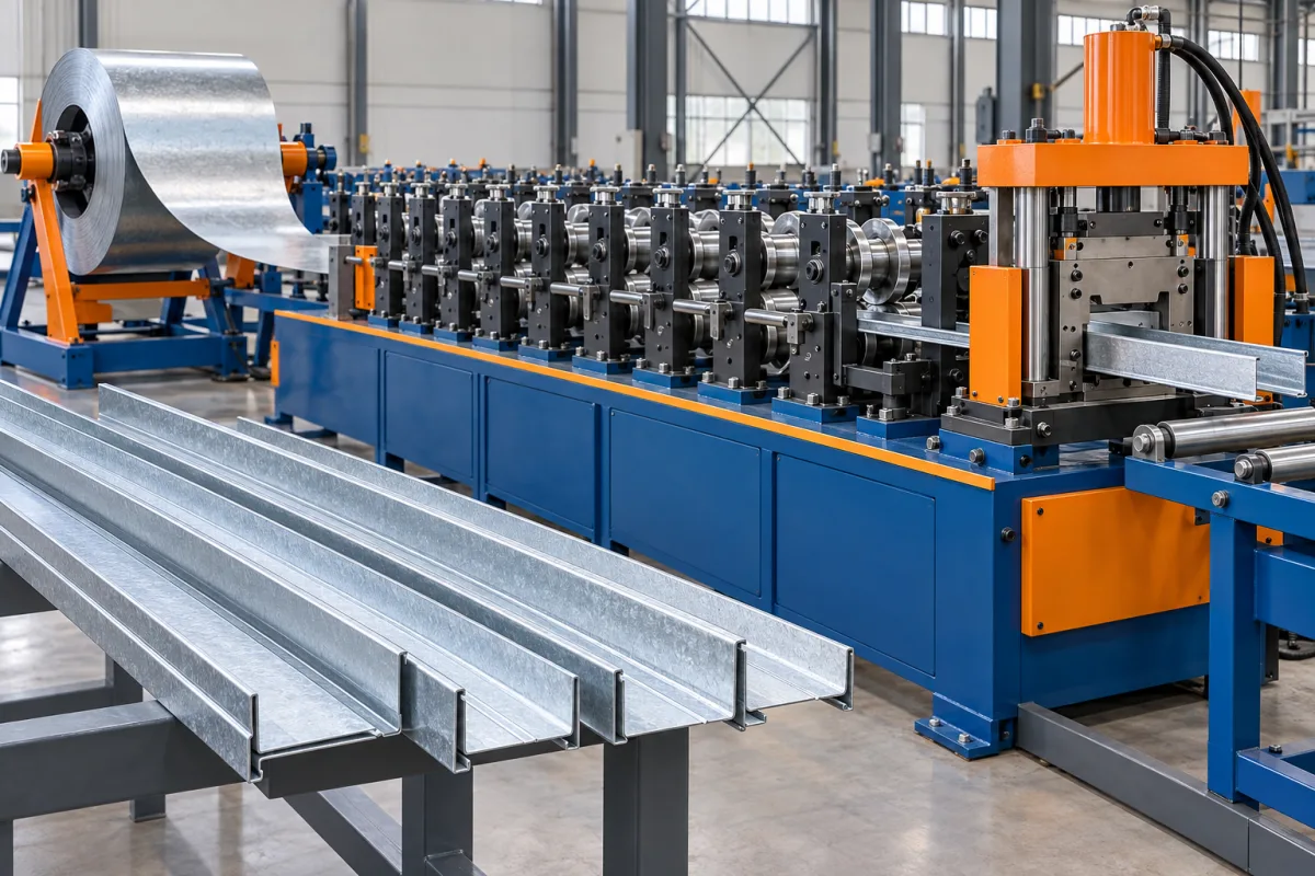
A ceiling carrying channel roll forming machine makes the specified member that carries or supports other components in a suspended ceiling arrangement. The exact section can vary by system, so carrying channel is a functional description rather than a universal shape. Its hanger, connector and furring interfaces should guide the machine specification.
The product should be distinguished from the board-facing furring channel and from exposed T-grid members. These components may work in the same broad ceiling market but have different sections, connections and acceptance needs.
What role does the carrying channel perform?
Use the selected ceiling-system drawing to identify what hangs from the channel and what supports it. Show hangers, cross connectors and any splice arrangement. The machine needs the geometry that makes those interfaces fit; system design determines their permitted layout and loading.
Do not specify the member only by an outside width and depth. A small return or lip can be the feature that retains a connector. Omitting it from the drawing can produce a consistent but incompatible channel.
Which section details should be controlled?
Define the web or crown, flanges, returns, radii and openings. Identify the surfaces used for hanger and connector engagement. Include installed orientation and a consistent measurement method.
- Overall depth and width.
- Internal openings needed by connectors.
- Return or lip dimensions.
- Splice and end interfaces.
- Material thickness and coating.
Use actual mating components during review. A connector borrowed from a visually similar system should not become the approval reference by convenience.
How does it differ from a furring channel?
The carrying member and the board-facing member can have different roles and profiles. Their connection may use a clip or another defined interface. The two drawings should be considered together where one depends on the other for fit.
If both products are to be manufactured, list them as separate variants with their own tools and acceptance samples. A shared lightweight-steel material does not mean one unchanged roll set produces both.
How is the carrying section manufactured?
Coil entry and guidance feed the strip into progressive forming stages. Any specified holes, slots or surface details are added by the agreed process. The completed section is cut to length and transferred onto supports for inspection and bundling.
Ask how close returns and connector openings are protected during cutoff. Local deformation at the end can prevent a splice from fitting even if the mid-length section is correct. Inspect both areas in the trial.
What material and feature requirements matter?
Specify grade, base-metal thickness and coating rather than a generic galvanized-steel label. Include any punching pattern and its relationship to member ends. The actual material should be used in forming and connector-fit trials.
Check bend condition, feature edges and surface damage. Keep the approved material identity with the sample. A change in thickness or grade may affect the return and connector fit even when outside dimensions appear similar.
Can widths or depths be adjusted?
Only within the proposed tooling range. Changing a depth or return can alter the hanger or cross-connector interface, so it is not merely a cosmetic variation. Ask for a matrix of approved sections and the adjustments or tool exchanges required.
After a change, verify the intended connectors as well as the measured section. The first accepted member should satisfy the functional interface, not only a target outside width.
How should long channels and splices be checked?
Use agreed supports to assess straightness and twist. Demonstrate the normal stock lengths and inspect the ends for flare or crushing. Fit the intended splice where the system uses one.
Review bundle restraints and stack orientation. Lightweight returns can be distorted by packaging pressure. Recheck connector openings after normal handling to make sure the accepted part remains usable when delivered.
What does a ceiling-oriented acceptance trial contain?
- Confirm the carrying-channel drawing and material.
- Measure the section and functional openings.
- Inspect cut ends and feature positions.
- Fit intended hangers, cross connectors and splices.
- Assemble a representative ceiling-interface group.
- Check straightness and condition after bundling.
- Record accepted output and required size-change work.
Keep this manufacturing fit check separate from the ceiling system's load, fire or acoustic assessments. Those depend on the complete specified construction and cannot be inferred from a channel's appearance.
Frequently asked questions
Is every carrying channel the same cross-section?
No. The term describes a role in a ceiling system. Obtain the actual drawing and connector references before selecting tools or comparing nominal dimensions.
Can a hat-furring line make carrying channels?
Only if the proposed tools and material range cover the actual carrying section. The connection interfaces may differ even when both products are lightweight ceiling profiles.
Are hanger holes always punched?
The selected system determines the attachment method. Specify any required features explicitly rather than adding a generic hole pattern that may not belong to the design.
Why test a splice at the cut end?
Cutoff can locally alter the opening or returns. A splice that fits a mid-length sample may not fit the delivered end if that local condition is not checked.
What should be included in the enquiry?
Send the full section, material, lengths and intended hangers, connectors and splices. Add required variants and bundle format to define a complete manufacturing route.
Specify the carrying member through its connections
The most useful equipment brief links section dimensions to the ceiling components they retain. That provides a clear trial target and avoids confusing a generic formed channel with an assembly-ready carrying member.

Continue your research
- Ceiling & Furring Roll Forming Machines
- Furring Channel Roll Forming Machine
- Main Channel Roll Forming Machine
- Hat Furring Channel Roll Forming Machine
- Ceiling T Main Runner Roll Forming Machine
- Ceiling Cross T Roll Forming Machine
- How Ceiling roll forming machine Works
- How To Choose a Ceiling roll forming machine
- Ceiling roll forming machine Price: What Affects the Cost?
Configuration & specification inputs
Match the configuration to your section drawing, material and production requirements.
| Parameter | Requirement / confirmation needed |
|---|---|
| Profile geometry | System-specific carrying section with controlled hanger, connector and splice interfaces. |
| Material | Specified lightweight steel grade and coating with traceable trial material. |
| Thickness & grade | Approved base-metal thickness and section combinations for the selected ceiling member. |
| Process route | Guided entry, required features, carrying-section forming, protected cutting and bundling. |
| Cutting | Required lengths with usable end openings and undistorted splice interfaces. |
| Output | Accepted carrying members including connector checks, size changes and normal packaging. |
| Electrical supply | Site utilities matched to the carrying-profile forming and auxiliary package. |
| Acceptance | Functional openings, hangers, cross connectors, splices, straightness and condition after handling. |