
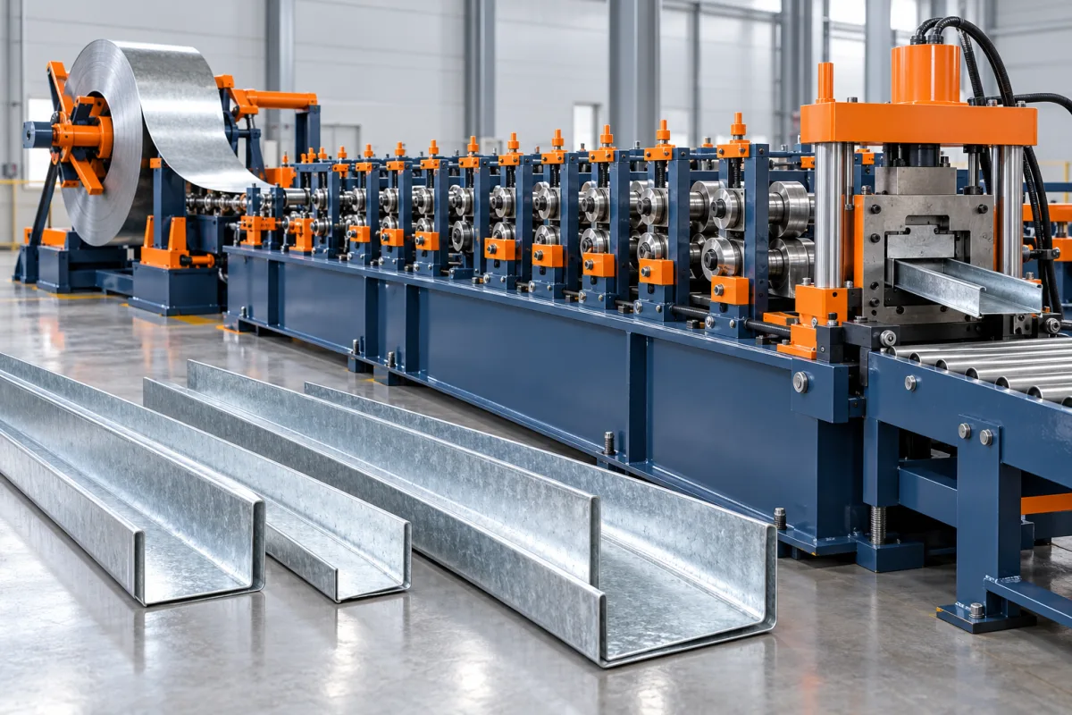
A main channel roll forming machine manufactures the principal carrier profiles used in a specified suspended-ceiling or lining framework. The channel connects with hangers, clips, secondary members or perimeter details, so the useful product is defined by those interfaces as well as its overall cross-section.
The phrase main channel is not a universal shape. In one system it describes an open cold-formed carrier; in another market, a different section or a visible T-grid runner may receive a similar name. Before comparing machinery, identify the actual ceiling arrangement and make sure every proposal addresses the same component.
How does a main channel differ from a furring channel?
In a two-level framework, the main carrier and the secondary furring member perform different roles and connect through the specified detail. The furring member may provide the board-fixing face, while the main carrier links the secondary members to the suspension arrangement. The exact configuration comes from the selected ceiling system.
Those roles do not establish one standard section size or material. Supply the carrier, furring and connector drawings together. A machine that forms a visually similar channel has not necessarily reproduced the dimensions that allow the intended assembly to fit.
Which interfaces should define the profile?
Identify every component that contacts the main channel: suspension clips, wires or other hanger arrangements, secondary channels, splices and perimeter connections. Show the surfaces that locate or retain those components. Small returns or flange angles can matter more to assembly than the broad web dimension.
- Carrier geometry: web, flanges, returns and bend radii.
- Suspension interface: the specified contact, hole or engagement feature.
- Secondary-member connection: clip clearance and locating surfaces.
- Splice: insertion depth, overlap or fastening pattern where required.
- Member condition: length, straightness, twist and finished ends.
Use consistent datums across those drawings. If each component is dimensioned from a different assumed reference, an apparently complete specification can still leave the actual fit ambiguous.
What information is needed before tooling design?
Provide the complete section family and identify which variants share a connection system. Include material grade, base-metal thickness, coating and strip-width requirements. List stock and project lengths separately if both are sold.
Samples of the intended connectors are useful during review, but they should correspond to the controlled drawings. If a commercial sample varies from the design, resolve the difference before approving tools. Otherwise the machine may be adjusted around an accidental sample condition rather than the intended product.
Clarify whether holes or slots are required in the channel itself. Some connections engage the formed geometry without such features, while others depend on a specified pattern. The equipment scope should follow the actual system instead of adding generic perforation capability without a purpose.
How does a main-channel production route work?
The line presents the coil, guides the strip, develops the channel through successive bends, produces the required length and collects the finished members. Feature-making, if needed, must maintain its relationship to the final section and cut ends. The detailed sequence depends on the proposed machine.
- Confirm coil identity and the released channel configuration.
- Load and guide the strip within the specified handling envelope.
- Perform required holes, slots or other included operations.
- Progressively form the web, flanges and functional returns.
- Cut and support the channel so its connection geometry remains usable.
- Inspect, count and group the accepted lengths.
Ask how the process controls the surfaces used by clips and splices. Those are the meaningful forming targets; roller count or machine length alone does not explain whether the line will reproduce them reliably.
Why must material combinations be reviewed together?
A section's grade, thickness, width and finish jointly define its forming duty. Changing one may alter springback, end behavior or connector fit. A catalogue range should therefore be expressed as approved combinations rather than unrelated minimum and maximum numbers.
Inspect coating condition at bends and contact surfaces with the actual material. Record the coil used for accepted trials. If a later batch becomes difficult to clip or splice, that record helps distinguish incoming-material variation from a changed machine setting or a different connector.
Do not convert a material trial into a ceiling load claim. Manufacturing the specified section and verifying the ceiling assembly's performance are separate tasks. The production brief should assign both responsibilities clearly without confusing one result with the other.
What changes when the carrier size changes?
Separate changes in web size, flange size and return geometry. A line may adjust one dimension while retaining the others, or it may require a different tool set. Request a capability matrix showing each permitted combination and the required guides, rolls and cutoff components.
If the same machine also produces furring or perimeter profiles, review each as a distinct configuration. A broad accessories package can be useful, but its changeover process must be realistic for the factory's order mix. Include tool storage and handling in the layout.
Demonstrate a change and return to the original carrier. Check the first accepted member after each transition, including clip and splice fit. Repeatable recovery matters more than a one-time setting reached during a carefully prepared demonstration.
How should a ceiling-framework fit trial be arranged?
Assemble a representative portion of the selected framework using production-intent carriers, secondary members and connectors. Follow the system's intended connection sequence. Check whether the components seat correctly and maintain their specified relative positions without improvised bending.
Inspect the channel at the connection and away from it. A connector can appear to fit while locally distorting a flange or forcing an incorrect alignment. Record those observations instead of judging the assembly solely from a completed photograph.
Keep this trial focused on manufacturing compatibility. Suspension spacing, loading, fire behavior and other project requirements must follow the applicable design and evidence for the ceiling system, not be inferred from the ease of assembly.
What should be checked at cut ends and splices?
Cut ends can affect insertion into a splice or the seating of a nearby connector. Examine local flare, burrs and deformation after normal collection. Compare the end section with a measurement farther along the same member to locate the deviation.
Where a splice is part of the product, test it with members from the trial rather than a specially selected short piece. Confirm the required overlap or insertion condition and any fastening features. A fitting that can be forced onto one end is not proof that routine production will assemble consistently.
How should long members be collected and packed?
Support the intended length range through inspection and bundling. Main carriers may appear robust in cross-section yet still be altered by poor lifting or unsupported storage. Define the bundle orientation and the handling method before judging finished straightness.
Labels should distinguish size, thickness, length and product reference. Similar carriers for different connector systems should not be mixed merely because they nest together. For project orders, include the identification needed to separate framework zones or assembly sets.
What determines useful output and project cost?
Evaluate accepted bundles over an order containing the relevant lengths and changes. Coil replacement, feature-making, cutoff and collection all affect the practical result. The longest uninterrupted run is not necessarily representative of the factory's regular schedule.
Compare packages that include the same tools, feature operations, handling and inspection equipment. Clarify whether connectors and splices are purchased, made separately or included elsewhere in the project. A main-channel former alone does not manufacture every component of the suspension system.
What should acceptance document?
- The approved carrier and connection drawings.
- Actual trial materials and configuration settings.
- Cross-section, length, straightness and end-condition measurements.
- Clip, secondary-member and splice fit results.
- Performance of required size or profile changes.
- Bundle quality and identification after normal handling.
- Accepted output, rejected parts and unresolved deviations.
Retain a complete reference assembly where practical, together with the measurement record. It gives production and quality staff a clearer benchmark than an isolated loose channel whose mating components have been lost.
Frequently asked questions
Is a main channel the same as a T-grid main runner?
Not necessarily. Names vary between markets and ceiling systems. Supply the cross-section and assembly drawing so the proposal addresses the intended open carrier, T runner or other profile rather than relying on terminology alone.
Can one main channel accept every furring clip?
No. Clip engagement depends on the actual contact geometry and material. Use the specified connector during tooling review and acceptance. Similar nominal widths do not establish interchangeability.
Does the line also make suspension components?
Only if those products and operations are explicitly included. Hangers, clips and splices may require separate equipment or purchased components. Define the complete manufacturing boundary before comparing quotations.
Should longer carriers be included in the trial?
Yes, when they form part of the intended catalogue. Long products expose support, straightness and handling questions that a short sample can miss. Inspect them in the agreed support condition after normal collection.
Can the channel be changed to increase ceiling capacity?
Any design change needs the responsible system engineering review. The machine can be assessed for making the revised drawing, but a forming adjustment alone does not establish a new load rating for the assembly.
What should be prepared for an enquiry?
Provide carrier, furring, clip and splice drawings, material combinations, lengths and order quantities. Add handling and acceptance requirements. This makes the equipment proposal specific to the ceiling framework being produced.

Continue your research
- Ceiling & Furring Roll Forming Machines
- Furring Channel Roll Forming Machine
- Ceiling T Grid Roll Forming Machine
- Hat Furring Channel Roll Forming Machine
- Ceiling Carrying Channel Roll Forming Machine
- Ceiling T Main Runner Roll Forming Machine
- How Ceiling roll forming machine Works
- How To Choose a Ceiling roll forming machine
- Ceiling roll forming machine Price: What Affects the Cost?
Configuration & specification inputs
Match the configuration to your section drawing, material and production requirements.
| Parameter | Requirement / confirmation needed |
|---|---|
| Profile geometry | Carrier web, flanges, returns and hanger, clip and splice interfaces |
| Material | Drawing-specified ceiling-carrier grade and coating |
| Thickness & grade | Pair thickness and strip width with each approved carrier configuration |
| Process route | Coil identification, required features, progressive channel forming, cutoff and grouping |
| Cutting | Inspect end flare and the ability to receive the specified splice |
| Output | Accepted labelled carrier bundles with verified framework compatibility |
| Electrical supply | Specify utilities after selecting feature, forming, cutoff and collection equipment |
| Acceptance | Measure carrier geometry and assemble production-intent hangers, secondary members and splices |