
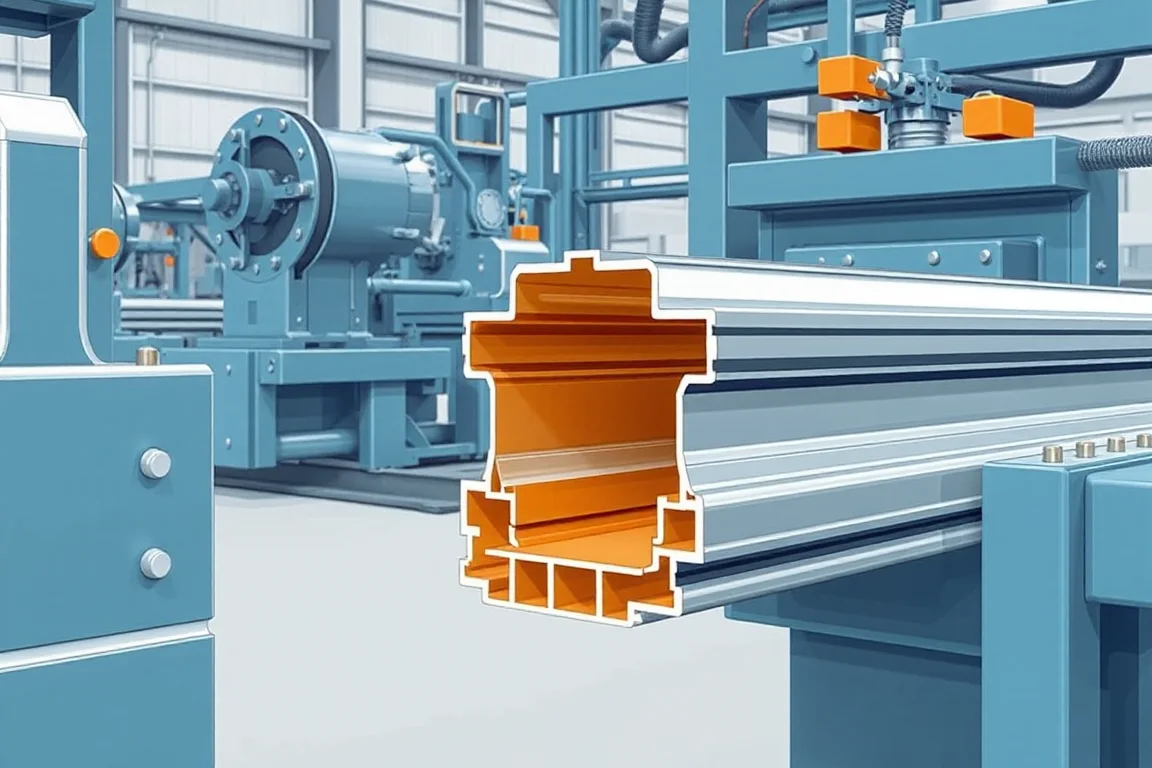
Ceiling-profile tooling must reproduce the surfaces that connect and support the selected ceiling system. A furring channel's flange, a runner's slot and a cross tee's connector have different functions. The tooling review should identify those functions before treating every product as a variation of one narrow channel.
Define construction before choosing a tooling concept
Show whether the component is made from one strip or includes a cap, joined layers or a separate connector. Each construction creates a different set of forming and assembly interfaces. A longitudinal section alone may not describe the complete product.
Provide controlled drawings for continuous geometry and end details. Include the relationship to mating components. This establishes which dimensions must be preserved through forming, feature-making and cutting.
Identify bearing and connection surfaces
A flange that supports lining, a hanger contact and a cross-connection slot need their own references. Prioritize the functional dimensions in the inspection plan rather than measuring every visible edge without a clear purpose.
Use the specified mating hardware during development. A generic clip or another supplier's cross tee may not be equivalent even if nominal dimensions appear similar. Tool acceptance should verify the intended system interface.
Develop thin sections progressively
The forming sequence must suit the material and complete geometry, including small returns and bearing surfaces. Ask the tool designer to explain the important development choices and the combinations supported. Stand count alone is not evidence of a better result.
Inspect representative complete lengths after normal handling. Thin sections can be deformed outside the mill, so the test should distinguish tooling output from discharge damage. A carefully selected short coupon may miss that distinction.
Coordinate cap tools with the runner body
Where a decorative cap is part of the design, identify its material feed and forming or joining route. The cap and body must maintain the specified relationship along the runner. Review their combined geometry rather than approving each strip independently.
Appearance checks should follow the complete route. A neat cap at the forming exit may become marked during cutting or packing. Include visible-face alignment and finish in the tooling acceptance conditions.
Feature tools need final-component datums
Slots, hanger holes and connector preparations must be located from the approved references. Determine where they are made and how their final position is checked after forming and cutting. Local feature accuracy is not enough if the complete runner's spacing is wrong.
For a grid, assemble representative main and cross members to verify the relationship. A slot pattern that looks regular can still produce an incorrect module or incompatible end connection. The product's actual interface is the acceptance target.
Separate length changes from connector changes
Changing a cut length may also require a different feature pattern or end arrangement. Ask which parameters and tools change for each product variant. A machine with adjustable length is not automatically capable of every cross-member configuration.
Keep connector tooling identified by design and revision. A small end-detail change can affect engagement with another component and may require a system review. Do not treat it as a cosmetic modification.
Make the supported profile matrix explicit
List the channel or runner variants, materials and required tools. Distinguish adjustments within one family from a new construction requiring separate equipment. This is especially important when a supplier offers several ceiling-related products on one platform.
A route that changes between furring channels and wall angles may still lack the cap and connector functions needed for a T-grid. The matrix should make these boundaries understandable to purchasing and production staff.
Validate complete recovery after a change
Choose a meaningful transition and return to a previously accepted component. Check geometry, features, mating fit and finish using the same inspection method. Tool movement alone does not demonstrate recovered product quality.
- Identify component drawings and material streams.
- Inspect the continuous section and required features.
- Check cut ends and any connector operation.
- Assemble the specified interfaces.
- Inspect after collection and packaging.
- Repeat relevant checks after configuration recovery.
Use a connector-change scenario during procurement
Include an inspection-method review with that scenario. Decide how the end reference, connector projection and receiving-slot position are measured and how the assembled sample is supported. If one team checks a free component and another forces it into a fixture, their results may appear inconsistent for reasons unrelated to the tools. The delivery documentation should preserve the method used to accept the revised component.
Keep a distinction between tooling approval and ceiling-system approval. Manufacturing the revised connection accurately does not establish that it retains the original system's performance. The responsible product design process must address that question separately. The tooling supplier can provide dimensional and process evidence, while the buyer ensures that the correct approved design is the one being manufactured. This boundary prevents an apparently small production change from becoming an undocumented product substitution.
Suppose a runner retains its visible face width but adopts a different end connection. Ask which punches, end tools, fixtures and inspection references change. The unchanged face does not prove that existing tooling can make the revised complete component.
This scenario helps reveal whether the supplier has priced only longitudinal forming or the full assembly-ready product. It also establishes how future changes will be reviewed and documented, reducing the risk of mixing incompatible old and new components.
Frequently asked ceiling tooling questions
Can one channel tool set make all ceiling profiles?
No. Construction, bearing surfaces, returns and connection details differ. Obtain a defined supported matrix instead of relying on the broad ceiling category.
Is visible face width enough to approve a T-runner?
No. Body geometry, feature positions, connectors and their assembly relationships also matter. Inspect the complete component and mating sample.
Why include packaging in a tooling trial?
It shows whether the formed product retains usable geometry and finish through the intended route. This helps distinguish a tooling issue from later handling damage.
What should accompany the tools?
Component and interface drawings, material combinations, tool identification, setup references and acceptance evidence. Include the end-detail and mating-component revisions used in trials.
Continue your research
- Ceiling & Furring Roll Forming Machines
- Furring Channel Roll Forming Machine
- Main Channel Roll Forming Machine
- Hat Furring Channel Roll Forming Machine
- Ceiling Carrying Channel Roll Forming Machine
- Ceiling T Main Runner Roll Forming Machine
- How Ceiling roll forming machine Works
- How To Choose a Ceiling roll forming machine
- Ceiling roll forming machine Price: What Affects the Cost?