
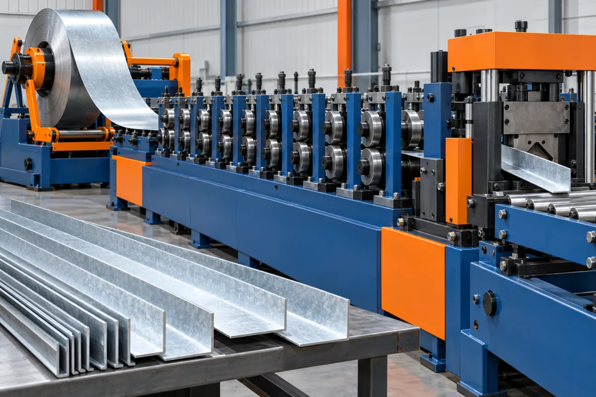
A wall angle roll forming machine produces perimeter profiles used where a selected ceiling or lining system meets a wall. The familiar L-shaped trim is only one possibility: equal and unequal legs, hems, steps or other edge details can change the product's support function, visible appearance and forming requirements.
Because these profiles are often exposed along a long boundary, a useful production specification gives equal attention to geometry and finish. A straight, clean-looking angle that matches the ceiling system can be more valuable than a high-speed output of parts that need correction, repainting or difficult sorting.
What does a perimeter wall angle do?
The angle provides the boundary detail defined by the ceiling or lining design. One leg relates to the wall fixing, while the other forms the intended visible or supporting edge. The exact role depends on the selected system, including whether the ceiling components bear on, overlap or simply meet the trim.
Do not infer load support or movement behavior from the word angle. The profile must follow the system drawing and installation detail. The equipment enquiry should identify that detail so the machine produces the right legs, offsets and finish rather than an arbitrary right-angle strip.
Which wall-angle family should be specified?
An equal-leg angle is geometrically different from an unequal-leg trim, even if both share an included angle. A hemmed edge adds another forming requirement. Stepped or shadow-line perimeter profiles introduce further bends and a different visible relationship with the ceiling plane.
List each variant with a drawing and identify which are expected to share tools. A broad request for wall angles can otherwise result in proposals that cover very different products. If U-shaped, W-shaped or other perimeter sections are required, include them explicitly instead of assuming that an L-angle line will make them through adjustment alone.
- Leg widths and their measurement convention.
- Included angle and bend radius.
- Hems, returns, steps or shadow-gap features.
- Fixing holes or slots where specified.
- Visible surfaces and coating orientation.
- Lengths, end condition and packing format.
How should the visible finish be defined?
Identify which faces are exposed after installation and which surfaces may contact the tools or packing. Include the actual prefinished material in trials. A sample made from uncoated stock cannot demonstrate the handling result for the intended painted trim.
Agree how scratches, edge marks and finish consistency will be inspected. Use consistent lighting and support conditions rather than comparing unrelated photographs. Where protective film is required, state when it is applied and its condition during cutting, inspection and packing.
Color changes are also production changes. The line and warehouse need a reliable way to clear the previous material, identify the new order and prevent visually similar finishes from being mixed in one pack.
What is the production sequence?
The coil is presented to controlled entry guides, then the forming passes progressively develop the corner and any additional edge features. Required holes or slots are made in the specified sequence. Cutting and collection complete the member while preserving its angle and appearance.
- Confirm the material, color, visible-face orientation and product drawing.
- Load and guide the strip without avoidable surface damage.
- Produce any included fixing features.
- Develop the principal bend and required hems or steps.
- Cut the ordered length with suitable profile support.
- Inspect, nest and pack the trim with its finish protected.
The detailed order can vary with the equipment. Ask how the proposed route handles the visible edge and how it supports unequal legs during forming and cutoff. Those details are more informative than a generic list of motors and stands.
Why can a simple angle still be difficult to produce consistently?
The two legs are not always mechanically balanced, particularly in unequal-leg profiles. Material response and forming sequence can influence twist, bow and the included angle after release. The finished condition should therefore be measured on normal production lengths, not just a short cross-section.
A narrow visible leg may also make small edge or finish defects conspicuous. Inspect the trim after collection to determine whether a mark originates in forming, cutoff or nesting. Treat those observations separately rather than assuming that every defect requires a change to the main bend tools.
Use the approved material and a defined support method when comparing results. A flexible long trim can appear distorted simply because it is being held differently, which is why consistent measurement conditions matter.
What material combinations belong in the scope?
Specify grade or alloy, base-metal thickness, strip width, coating and finish for each family. Steel and aluminum should not be treated as interchangeable because their nominal thicknesses match. The proposed tooling and handling need to be reviewed for the actual material response and surface requirements.
Record material identity with accepted samples. If a later batch springs open, twists or shows coating marks, the investigation should compare incoming stock as well as machine settings. This is especially useful when several colors or suppliers share the same product code.
Define the condition of slit edges where it affects the visible product or a hem. Incoming strip quality can influence the final result, so its requirements belong in the production agreement rather than being left entirely to the coil supplier's default practice.
Dedicated wall-angle line or shared perimeter-trim equipment?
A dedicated arrangement can suit a stable, high-volume angle family. A shared accessories line may be more appropriate for several perimeter shapes and smaller orders. Compare the frequency of changes and the complete first-good-product recovery, not only the number of profiles listed as possible.
Ask which changes are adjustments and which need rolls, guides or cutting components. A leg-width change may be simpler than a new hem or step geometry, but that depends on the proposed design. Request a configuration matrix and demonstrate the transitions important to the business.
Include tool storage, safe handling and setup references. A flexible line remains practical only when operators can restore each trim without lengthy trial-and-error correction.
How should holes, slots and ends be handled?
If the perimeter detail requires fixing features, specify their shape, pitch and relationship to the ends. Identify which leg receives them and how the finished product is referenced. A repeated hole pattern should not be assumed suitable for every installation detail.
Cut ends should meet the agreed condition without crushing a hem or leaving an unacceptable flare. If corner joining or mitred ends are part of the commercial product, define whether they are produced inline, in a separate operation or by the installer. A straight-length former does not automatically include corner fabrication.
Inspect features and ends after normal handling. A correct punch or cut in isolation is not sufficient if the collected trim is damaged before packing.
What packing details protect saleable output?
Wall angles are often nested closely, so contact points deserve attention. Define orientation, separators where required, pack quantity and the force applied during securing. The packing trial should check that profiles remain straight, separable and free of unacceptable finish marks.
Labels need to distinguish section, length, material and color. Similar shades can be difficult to identify once a job reaches site. Use a clear batch or order reference and keep rejected or setup pieces outside the accepted packing flow.
For a planning example, a carton of 40 trims at 3 metres each contains 120 metres of finished product. That simple quantity helps compare packing and stock requirements, but it says nothing about the machine's production rate without the full operating cycle.
How should output and price be evaluated?
Measure accepted packed lengths during a representative order with the specified finish. Coil and color changes, cutting frequency, inspection and boxing may control the practical rate. A faster forming pass is not an improvement if the visible surfaces are damaged downstream.
Compare quotations for the same profile family, material range and packing outcome. Include payoff, tools, feature operations, cutoff, collection, inspection aids and commissioning. State whether future perimeter variants require additional tools or a separate production arrangement.
What should acceptance include?
- Leg widths, included angle, radii and additional edge features.
- Straightness and twist on representative finished lengths.
- Hole or slot positions where included.
- Cut-end condition and any required joining interface.
- Visible-face inspection using the actual finish.
- A relevant size or profile change followed by accepted recovery.
- Condition of a normal packed bundle after handling.
Retain reference pieces and the agreed inspection conditions. This helps the production team distinguish a real deviation from a different viewing angle or support arrangement during later checks.
Frequently asked questions
Can the line make both equal and unequal angles?
A configured line may cover both, but the permitted dimensions and change parts must be stated. Unequal legs can require a different forming and straightness review. Demonstrate the actual profiles rather than relying on the general angle category.
Does a wall-angle line also produce shadow-gap trims?
Only where the additional bends and edge details are included in the tooling scope. A stepped perimeter section is not simply an L angle with another name. Supply its complete drawing for review.
Are fixing holes always necessary?
No. They depend on the chosen perimeter detail and installation method. Specify the required feature pattern rather than adding punching automatically. Plain trim and perforated trim should have clearly separated production requirements.
Can prepainted material be formed without protective film?
That depends on the material, tooling, handling and agreed appearance result. Trial the actual finish and packing process. Do not assume that film is either always essential or always unnecessary.
Why inspect after packing?
Nesting and securing can scratch finishes or distort light sections. The saleable product is the delivered pack, not only the trim leaving the rolls. Including packing in acceptance makes the trial more representative.
What should be supplied for a quotation?
Provide the section family, materials, finishes, lengths, fixing features and packing requirements. Add expected order and color changes. Those details allow a practical comparison of dedicated and shared perimeter-trim production.

Continue your research
- Ceiling & Furring Roll Forming Machines
- Furring Channel Roll Forming Machine
- Main Channel Roll Forming Machine
- Hat Furring Channel Roll Forming Machine
- Ceiling Carrying Channel Roll Forming Machine
- Ceiling T Main Runner Roll Forming Machine
- How Ceiling roll forming machine Works
- How To Choose a Ceiling roll forming machine
- Ceiling roll forming machine Price: What Affects the Cost?
Configuration & specification inputs
Match the configuration to your section drawing, material and production requirements.
| Parameter | Requirement / confirmation needed |
|---|---|
| Profile geometry | Equal or unequal legs, included angle, hems, steps and fixing features |
| Material | Specified steel or aluminum with the actual visible-face finish |
| Thickness & grade | Approve material and thickness combinations for each perimeter profile |
| Process route | Protected coil guidance, optional fixing features, progressive angle and edge forming, cutoff and packing |
| Cutting | Check end condition without crushing hems or distorting unequal legs |
| Output | Accepted packed trim lengths including color and section changes |
| Electrical supply | Confirm complete-line supply requirements for the selected forming and packing scope |
| Acceptance | Measure legs and angle, inspect long-length twist and finish, and verify condition after nesting and packing |