
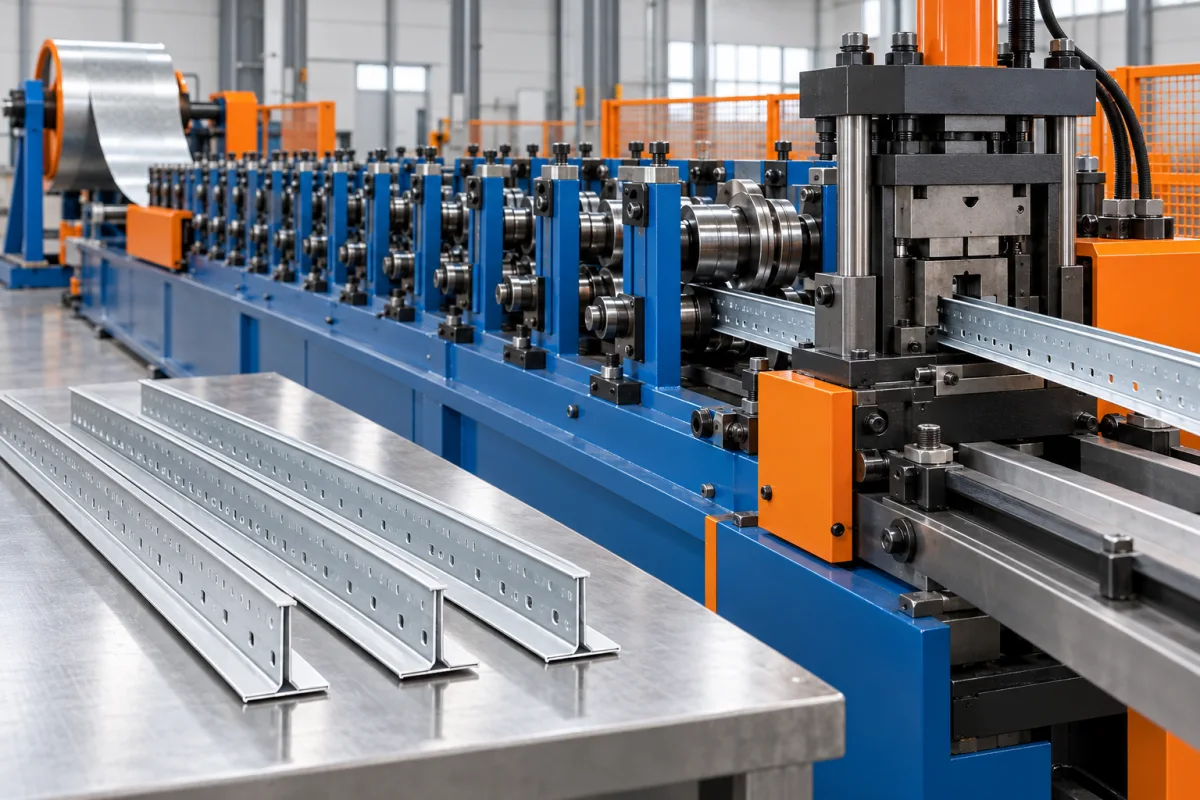
A ceiling T main runner roll forming machine produces the principal T-shaped member in the specified exposed ceiling grid. The runner combines a vertical body with the visible lower flange, connection openings and end-splice details. Those features must work with the selected cross tees and suspension arrangement.
This is a more specialized product than a plain T-shaped strip. Depending on the design, the route may involve a formed body, a separate decorative cap, punching and end-connector operations. The equipment scope should identify how the complete saleable runner is produced.
What defines the main-runner section?
Show the vertical body, top bulb or other stiffening geometry, lower flange and visible face. Identify whether a separate cap is used and how it is retained. Dimensions should distinguish the metal body from the finished exposed surface.
Include material specifications for each strip or component. A capped runner may involve different surface requirements from its structural body. The proposal should not treat all feed material as one unspecified coil.
How does the main runner differ from a cross tee?
The main runner establishes the principal grid line and has its own suspension and splice interfaces. Cross tees connect into specified openings along it. The two products may share a visible flange width but have different body, feature and end details.
If both will be manufactured, specify separate drawings and tooling scopes. A machine that forms the main-runner body does not automatically complete cross-tee end connectors or every grid-system feature.
Which slots and holes control grid assembly?
Define cross-tee connection openings, suspension features and any other designed cutouts. Their positions must be registered to the runner ends and the grid module. A correct overall length cannot compensate for an incorrect slot pattern.
- Show the reference end and feature spacing.
- Identify opening geometry and orientation.
- Define required solid or special zones.
- Include matching cross-tee connector samples.
- Record any expansion detail required by the system.
Do not copy a slot layout from another grid simply because its module appears similar. Connector engagement and system details need their own approved references.
How should body and cap production be coordinated?
Where a separate cap is used, the route must align it with the formed body and retain it according to the product design. Specify visible finish, edge appearance and how the cap behaves at the ends. A plain-body sample does not establish finished-runner quality.
Ask for the actual forming and joining sequence, including feature operations and cutoff. Identify any cap feeding or end-finishing equipment omitted from a basic forming package. The quotation should cover the complete runner intended for sale.
What should end-splice acceptance include?
Use the intended mating runner and end connector. Check engagement, alignment of the lower visible flange and the resulting feature pattern across the joint. The splice should be evaluated as an assembly rather than two separate end measurements.
Record any unexpected forcing or local adjustment. A connection that can be made only after reshaping a tab or trimming an end is not a repeatable acceptance result for normal production.
How should visible-face quality be inspected?
Specify coating or finish and the viewing condition for the exposed flange. Inspect cap alignment, edges and marks after the complete process. A finished ceiling makes repeated surface differences visible, so consistency across multiple members matters.
Repeat checks after normal bundling. Restraints or stacked contact can mark the visible face or distort the flange. The delivery-ready runner should meet the same appearance and fit references used at the machine exit.
What changes between grid variants?
Different flange widths, body heights, module patterns or connectors may require new tools and programs. Ask for a variant matrix covering body forming, cap handling, punching, end operations and cutoff. A common visible width does not guarantee common connector tooling.
Demonstrate changeover through a completed grid connection. Include first-good-runner inspection and startup waste. This gives a realistic comparison between shared equipment and dedicated routes for high-volume variants.
What should the acceptance grid demonstrate?
- Measure body, flange and visible-cap geometry.
- Verify feature spacing from the reference end.
- Join main runners through the specified splice.
- Connect representative cross tees.
- Check grid module, alignment and visible intersections.
- Inspect finish after normal packaging.
- Record accepted complete runners and changeover work.
Manufacturing fit is distinct from the complete ceiling system's loading or fire classification. Such performance belongs to the specified assembly and its verification, not a general T-runner machine description.
Frequently asked questions
Is the main runner just a folded T section?
No. Its feature pattern, splice, cross-tee interface and visible finish are essential parts of the product. The equipment must address the complete runner design.
Does every runner use a separate cap?
Follow the selected product construction. If a cap is used, specify its material, finish, retention and end condition as part of the manufacturing scope.
Can cross tees from another grid be used?
Do not assume compatibility. The connector and opening geometry should be approved together, and the trial should use the intended components.
Why check the feature pattern across a splice?
The joined runners must preserve the intended grid layout. Correct spacing on isolated pieces does not prove that their end relationship produces the correct assembled module.
What is a useful first trial?
A small grid containing joined main runners and representative cross tees, made from production-intent materials. It tests the interfaces that a loose runner sample cannot show.
Approve the runner as part of the grid
A complete main-runner brief connects the formed body, visible face, feature registration and connectors. That provides a practical equipment scope and an acceptance test centered on assembled ceiling components.

Continue your research
- Ceiling & Furring Roll Forming Machines
- Furring Channel Roll Forming Machine
- Main Channel Roll Forming Machine
- Hat Furring Channel Roll Forming Machine
- Ceiling Carrying Channel Roll Forming Machine
- Ceiling Cross T Roll Forming Machine
- How Ceiling roll forming machine Works
- How To Choose a Ceiling roll forming machine
- Ceiling roll forming machine Price: What Affects the Cost?
Configuration & specification inputs
Match the configuration to your section drawing, material and production requirements.
| Parameter | Requirement / confirmation needed |
|---|---|
| Profile geometry | Approved main-runner body, bulb or stiffening detail, visible flange and cap construction where used. |
| Material | Separately specified body and visible-cap materials, coatings and finishes. |
| Thickness & grade | Component-specific thicknesses reviewed through forming, capping and connector operations. |
| Process route | Body forming, specified cap integration, registered features, end operations, cutting and packaging. |
| Cutting | Runner length and end-splice geometry preserving the assembled grid-module relationship. |
| Output | Accepted complete main runners including feature and cap checks and required variant changes. |
| Electrical supply | Utilities for body forming, cap feed, punching, end finishing and transfer equipment. |
| Acceptance | Body and face geometry, slot spacing, joined main runners, cross-tee fit and visible grid alignment. |