
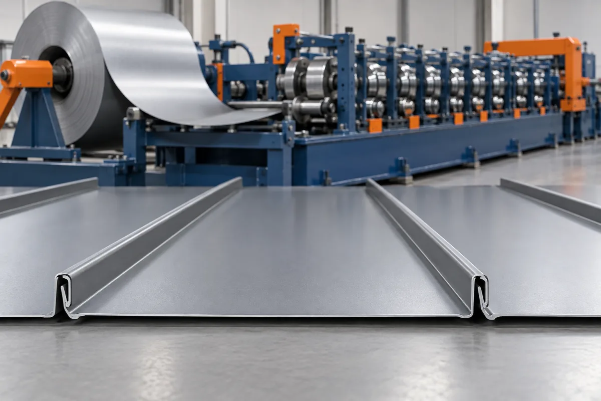
A 25 mm snap lock standing seam machine forms a roof-panel family with a nominal 25 mm seam height and complementary edges designed to engage by the specified snap-lock method. Seam height alone does not define the lock. The return shape, opening, attachment arrangement and panel pan all need to be established from the actual system drawing.
This application differs from a mechanically closed standing seam, where a separate seaming operation completes the joint. It also needs to be distinguished from a nominal one-inch profile: one inch is 25.4 mm, and neither label proves that two manufacturers' joint shapes are interchangeable.
What must the 25 mm joint drawing show?
Provide both mating edges in their unassembled and engaged positions. Mark seam height using the agreed datum and identify the returns and contact areas controlling engagement. Include the pan width and any ribs or striations required in the visible face.
Show the attachment method as well. A separate clip and a slotted fixing flange are different arrangements even if the finished joint has a similar height. The tooling and any feature-making equipment must match the chosen design.
How does snap lock differ from mechanical lock?
A snap-lock system is designed to engage its complementary formed edges using its specified installation sequence. A mechanically seamed system is designed for additional closing of the seam. Their edge preparation and acceptance checks should not be mixed.
Do not assume that a tight snap fit can be approved by running an unrelated seamer over it, or that a mechanical-lock profile becomes snap-lock by changing its height. Use the intended joint and attachments throughout the manufacturing review.
Which inputs establish the production envelope?
- Complete 25 mm joint and pan drawing.
- Clip or fixing-flange detail and actual mating samples.
- Material grade or alloy, thickness and coating.
- Panel widths, lengths and optional face features.
- Specified holes, slots, notches or end preparation.
- Factory or portable production arrangement.
Pair material and thickness with each profile variant. A broad material list is not a substitute for a reviewed matrix because a tight return can behave differently when material properties change.
How is the shallow snap-lock seam formed?
Guided strip passes through progressive stages that form the pan and develop the complementary edges. The forming sequence must leave the required opening and return geometry after material springback. The finished edge is therefore the result of tooling, material and setup together.
Cutting and discharge must preserve those small functional features. Check the joint near both ends of the panel, where cutoff or handling can change engagement even when the mid-length section is acceptable.
How should clips or slotted flanges be integrated?
For a clipped system, use the intended clip drawing and samples during tooling approval. Check the relevant contact surfaces and assembly sequence with the actual material. Similar clip height does not establish compatibility.
For a fixing-flange system, specify flange geometry and any slots, including their relationship to cut ends. Identify the feature-making equipment and its position in the route. The words snap lock do not automatically include punching or all required end preparation.
Can seam height or pan width be changed?
Pan-width adjustment and seam-height change are different requirements. A machine may support several widths with one joint while needing different tools for another seam. Ask for a configuration matrix showing the supported combinations and change parts.
Demonstrate changes through the first accepted panel and engaged joint. Include guides, cutoff support and any feature programs in the process. A correctly displayed dimension on the controller does not prove the new mating edges have been recovered.
How should finish and fit be inspected together?
Use production-intent coated material and define whether protective film is present during the assembly check. Inspect tight bends for coating condition and broad pans under agreed viewing conditions. Keep appearance observations separate from joint-fit measurements.
Assemble several panels using the intended attachments and sequence. Record unexpected resistance, looseness or local modification. A successful trial should not depend on forcing a sample into shape or substituting a different clip to make it fit.
What should the trial and quotation cover?
Include coil support, entry, forming, specified feature operations, cutting and takeoff. For portable use, define material loading, finished-length handling and site supply requirements. For factory use, review order sorting and stacking alongside the mill.
- Measure the unassembled seam and pan.
- Inspect cut ends and any fixing features.
- Engage panels with specified attachments.
- Check cover, joint continuity and finish.
- Run required material or width changes.
- Record accepted panels after normal handling.
Roof-system suitability remains tied to the approved assembly design. A 25 mm height by itself does not determine slope limits, wind performance or the correct support arrangement.
Frequently asked questions
Is 25 mm exactly the same as one inch?
No. One inch is 25.4 mm. More importantly, nominal height alone does not establish the lock shape or attachment compatibility. Use the exact controlled drawing for tooling and matching parts.
Does every 25 mm snap-lock panel use clips?
No. The chosen system may use clips or another specified attachment arrangement. Confirm the complete joint and fixing detail before deciding which tools and feature operations are needed.
Can the same line make a 38 mm seam?
Only if that exact profile is included in the equipment's engineered range. Request the roll, guide and cutoff changes and demonstrate the resulting joint with its intended attachments.
Should snap-lock panels be mechanically seamed?
Follow the selected system's installation method. Do not use an unrelated seaming operation to compensate for a poor snap fit or assume different seam families are interchangeable.
What is the best approval sample?
Retain individual measured sections and an assembled group using the actual clips or fixing arrangement. Together they document geometry, engagement and visible finish more clearly than a single loose sheet.
Specify the lock beyond its nominal height
A useful 25 mm snap-lock proposal connects the joint drawing, attachment and material to the forming and cutting route. That is the basis for repeatable engagement and a machine trial that reflects the roof panel actually intended for production.

Continue your research
- Standing Seam Roll Forming Machines
- Standing Seam Roll Forming Machine
- Snap Lock Standing Seam Machine
- 38mm Snap Lock Standing Seam Machine
- 1 Inch Mechanical Lock Standing Seam Machine
- 1.5 Inch Mechanical Lock Standing Seam Machine
- How Standing seam roll forming machine Works
- How To Choose a Standing seam roll forming machine
- Standing seam roll forming machine Price: What Affects the Cost?
Configuration & specification inputs
Match the configuration to your section drawing, material and production requirements.
| Parameter | Requirement / confirmation needed |
|---|---|
| Profile geometry | Drawing-controlled nominal 25 mm snap-lock seam with complete mating returns and pan geometry. |
| Material | Specified coated steel or alloy paired with production-intent attachment components. |
| Thickness & grade | Reviewed material-thickness matrix for the tight returns and agreed engagement method. |
| Process route | Guided entry, pan and snap-edge forming, specified fixing features, cutting and supported takeoff. |
| Cutting | Required lengths with functional seam ends and any notching explicitly included. |
| Output | Accepted panels after attachment and engagement checks under the stated changeover conditions. |
| Electrical supply | Factory or portable supply and auxiliaries matched to the selected line arrangement. |
| Acceptance | Unassembled seam dimensions, correct attachments, engaged cover, joint continuity and coating condition. |