
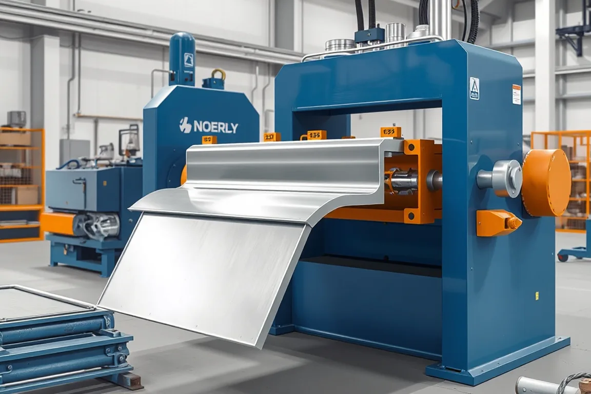
A scaffold frame profile roll forming machine produces open or tubular sections used in scaffolding components such as planks, toe boards, ledgers, and frame members. The machine bends a flat strip through a series of rolls to create a continuous cross-section. For a scaffold plank or frame profile, the cross-section often includes ribs or stiffening features, an anti-slip pattern, and interfaces for hooks, end plates, or support brackets. The roll forming machine is only one part of the production route; joining, finishing, and system approval are separate operations and responsibilities.
What Counts as a Scaffold Frame Profile
The term scaffold frame profile covers any formed sheet section that becomes part of a scaffold frame or platform. A plank profile, for example, is usually an open channel with raised ribs and a textured walking surface. A frame upright or ledger might be a closed tube, which normally requires tube mill production and welded end fittings rather than roll forming from flat strip. The drawing must clearly show whether the component is an open formed section or a tube, because that choice changes the machine type, tooling, and joining method.
Interface features are part of the profile definition. Holes for hooks, slots for locking pins, embossed anti-slip dimples, and end plate attachment points all influence how the roll forming line is configured. These features may be punched or embossed before forming, after forming, or in a separate press. The sequence matters because forming can distort holes or stretch material in ways that affect fit-up.
Material and Thickness Inputs the Buyer Must Define
The base-metal grade, thickness, and coating must be specified before a roll forming line can be quoted or configured. Structural steel grades used in scaffolding have defined yield and tensile properties, and those properties influence the roll load, springback, and tooling design. Coating type also matters: pre-galvanized strip behaves differently from uncoated steel during forming because the coating can flake or crack at tight bend radii. If the finished component will be hot-dip galvanized after fabrication, the welding and venting provisions must be planned for the assembled part, not just the formed profile.
Thickness range is a machine selection requirement, not a performance claim. A machine that runs a thin plank rib profile may not have the roll diameter, shaft strength, or drive capacity to form a thicker frame section. The buyer should state the intended base-metal thickness and grade, and require the builder to confirm the operating window for that specific combination. Roll forming a demonstration profile in a different material does not prove capability for the production profile.
Forming and Embossing Sequence for Plank Profiles
For a scaffold plank, the process route typically begins with punching or embossing the anti-slip pattern, followed by roll forming the plank or channel shape, then cutoff, and finally end fitting and joining. Embossing is often done on a press before the strip enters the roll former, because the raised pattern must be formed without being flattened by subsequent roll passes. If the pattern is rolled into the strip by the forming rolls themselves, the pattern depth and consistency depend on roll wear and strip thickness variation. Each approach has trade-offs in tooling cost, pattern quality, and changeover flexibility.
Punching for hooks, holes, or slots may also occur before forming. Pre-punching is generally simpler for hole location because the strip is flat and easy to locate, but the forming operation can distort hole shape or position. Post-forming punching requires access to the formed profile and may need dedicated fixtures. The buyer should decide which features are pre-punched, which are formed, and which are added after cutoff, then ensure the equipment scope covers each operation.
Cutoff Requirements and End Quality
Cutoff is a critical but often under-specified function. A scaffold plank or frame profile may need square ends, specific cut lengths, or end features that mate with hooks or end plates. The cutoff method must support the profile without crushing or deforming it. For open sections, a shear or die cutoff may be used; for closed or semi-closed sections, the cutoff tooling must avoid collapsing the shape. Cut length tolerance and end squareness affect assembly, especially if the component is welded to end fittings. Secondary operations such as deburring, notching, or hole piercing after cutoff may be required, and these should be listed in the equipment scope rather than assumed to be part of the roll former.
Joining and Assembly: A Separate Production Stage
Roll forming produces a profile; it does not produce a finished scaffold frame. Hooks, end plates, support interfaces, and any welded brackets are added in a joining stage. This stage may involve manual welding, robotic welding, riveting, bolting, or a combination. The joining fixtures, weld positioners, and inspection gauges for the assembled component are separate from the roll forming line. If the assembly is to be galvanized after welding, the joining process must account for drainage, venting, and distortion control during the coating operation.
Dimensional verification of the final frame is also separate. A formed plank profile might meet its own cross-section tolerances but still produce a frame that does not fit the intended system if end fittings are mislocated or welded at an angle. The acceptance criteria for the finished assembly, including reference dimensions and interface positions, should be defined by the scaffold system designer, not inferred from the roll formed sample.
Production Route Comparison: Roll Forming vs. Press Braking vs. Tube Mills
Roll forming is suited to long runs of a consistent open profile. It offers continuous production, good dimensional repeatability, and the ability to integrate punching and embossing. However, it requires dedicated tooling for each profile and has a significant setup time for changeover. Press braking is more flexible for low volumes or varied shapes, but it is slower and less consistent for long components. Tube mills produce closed sections and are appropriate for ledgers or uprights that are specified as tubes; they cannot produce open plank profiles with anti-slip patterns. The production route should be chosen from the approved scaffold-system drawing, not from a generic machine category.
Output and Quotation Scope: Define Accepted Output per Shift
Machine output should be defined as accepted finished components per shift, not just forming speed. A high forming speed is of little value if the joining, inspection, or packaging stages cannot keep up. The quotation should clearly state what is included: the roll forming line, the embossing press, the cutoff, the joining fixtures, the handling equipment, and the inspection gauges. The buyer should also ask for the assumed material, profile, and operating pattern used to calculate any output figure. Without that context, a quoted output number is not comparable between suppliers.
Electrical Supply and Installation Planning
The buyer must state the available voltage, frequency, and phase. The installed power of the complete line depends on the number and size of motors, including the main drive, any pre-punch or embossing press, the cutoff, and auxiliary equipment. A confirmed equipment schedule is needed before the electrical supply can be finalized. Installation planning should also consider foundation requirements, strip loading and handling, finished part removal, and space for the joining and inspection stations. These are not afterthoughts; they affect the layout and the achievable output.
Inspection and Acceptance Checks for Profiles and Assemblies
Inspection should cover both the formed profile and the finished assembly. For the profile, check the cross-section dimensions, rib height, anti-slip pattern depth, and straightness. For the assembly, check the positions of hooks, end plates, and support interfaces, as well as overall length and squareness. Load and slip requirements apply to the finished component and the scaffold system as a whole; they cannot be inferred from a formed sample alone. If the component is load-bearing, the relevant structural verification is a separate engineering activity based on the finished geometry and material properties.
Practical Checklist Before Approving a Production Line
- Identify the exact profile from the approved scaffold-system drawing: open section or tube, and all interface features.
- Specify the base-metal grade, thickness range, and coating, and confirm the forming window with the equipment builder.
- Decide the sequence for punching, embossing, forming, cutoff, and any secondary operations.
- Define the joining method and fixtures for hooks, end plates, and support interfaces.
- State the required accepted output per shift with the actual profile and material, not a demonstration substitute.
- Confirm the electrical supply and the installed power of the complete equipment schedule.
- Agree on inspection methods and gauges for both the formed profile and the finished assembly.
- Review the written equipment scope against all secondary operations needed for a finished, inspected component.
Frequently Asked Questions
Can one roll forming machine produce both plank profiles and ledger profiles?
Only if the machine and tooling are designed for the range of profiles and materials involved. A plank profile is typically a wide, shallow open section with ribs and an anti-slip pattern, while a ledger may be a tube or a narrower channel with different end interfaces. Changing between such profiles usually requires different roll sets, different cutoff tooling, and possibly different pre-punch or embossing arrangements. The buyer should list all intended profiles and materials and require the builder to confirm the changeover scope and the practical operating range for each.
Is the roll forming machine sufficient to produce a complete scaffold frame?
No. Roll forming produces the profile. A complete scaffold frame also requires joining end fittings, hooks, or plates; dimensional verification of the assembled frame; and any surface finishing or galvanizing. Those operations need their own fixtures, equipment, and inspection steps. The roll forming line should be specified as part of a production route, not as a standalone plant.
How should anti-slip features be formed on a scaffold plank?
Anti-slip features are commonly embossed or punched into the flat strip before the profile is roll formed, so that the pattern is not flattened by later forming passes. Alternatively, they may be formed by the rolls themselves, but this ties pattern quality to roll condition and strip thickness. The choice affects tooling cost, pattern consistency, and changeover time. The buyer should decide based on the required pattern depth, appearance, and production volume, then ensure the equipment scope includes the chosen method.
What does a supplier need to quote a scaffold frame profile roll forming machine accurately?
The supplier needs the profile drawing with all interface features, the base-metal grade and thickness range, the coating, the required production output in accepted finished parts per shift, the available electrical supply, and a clear statement of which operations the buyer expects the machine to perform. Also useful is information about the joining and finishing processes that will follow, because they can impose constraints on cut length, end quality, or hole position. Without these inputs, a quotation cannot be compared on a like-for-like basis.
How is acceptance testing handled for a roll forming line?
Acceptance testing should use the agreed production material and profile, not a simpler demonstration substitute. The buyer should inspect first-off pieces and a representative sample from steady production, using the agreed gauges and inspection methods. The test should also record changeover steps, setup scrap, and the time required for punching, embossing, cutoff, and unloading. The goal is to verify that the line can produce the required profile within the specified tolerances at a rate that supports the intended production plan, including downstream joining and inspection.
What is the difference between a plank roll forming machine and a scaffold frame profile roll forming machine?
A plank roll forming machine is configured for a specific family of plank profiles, often with anti-slip embossing and hook or end plate interfaces. A scaffold frame profile roll forming machine may be a broader description for equipment that produces various open or tubular frame members. In practice, the distinction is in the tooling and the interface features, not just the machine frame. Buyers should define the exact profiles and materials they intend to run, then select equipment that covers that range with confirmed changeover capability.
Distinguishing Nearby Topics
This page covers scaffold frame profiles in general, including planks and open frame members. Related pages address ringlock scaffold ledger roll forming, cuplock scaffold ledger roll forming, and scaffold toe board roll forming. Those pages deal with ledger profiles and toe board profiles, which have their own interface requirements and production routes. If the intended component is a ledger or a toe board, the tooling and equipment scope will differ from a general frame profile line.

Continue your research
- Scaffolding Roll Forming Machines
- Scaffold Plank Roll Forming Machine
- Scaffolding Deck Roll Forming Machine
- Ringlock Scaffold Ledger Roll Forming Machine
- Cuplock Scaffold Ledger Roll Forming Machine
- Scaffold Toe Board Roll Forming Machine
- How Scaffolding roll forming machine Works
- How To Choose a Scaffolding roll forming machine
- Scaffolding roll forming machine Price: What Affects the Cost?
Configuration & specification inputs
Match the configuration to your section drawing, material and production requirements.
| Parameter | Requirement / confirmation needed |
|---|---|
| Profile geometry | A scaffold frame profile must be identified as a tube or open formed section. The final frame’s joining, dimensional verification and system approval remain separate scope items. |
| Material | Specified structural steel with the required finish and joining procedure |
| Thickness & grade | Buyer to specify base-metal thickness and grade; operating range requires supplier verification. |
| Process route | Punch/emboss → plank or channel forming → cutoff → end fitting/joining → inspection |
| Cutting | Confirm profile-supported cutoff, cut lengths, end quality and any secondary operations. |
| Output | Define accepted output per shift with the actual profile and material. |
| Electrical supply | Buyer to state voltage / frequency / phase. Installed power requires a confirmed equipment schedule. |
| Acceptance | Check the completed assembly's reference dimensions, not only each loose member. Include the joining fixture and inspection approach where relevant. The machine scope should clearly distinguish member manufacture from complete frame production. |