
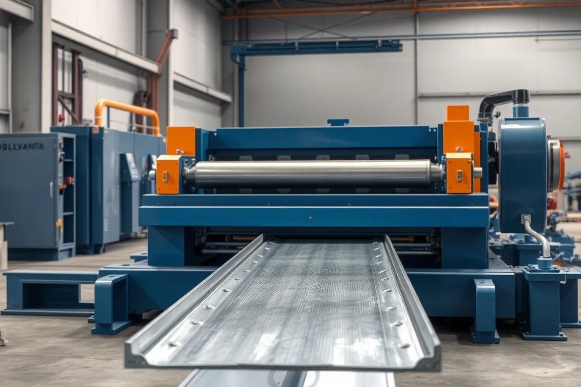
A scaffolding deck roll forming machine produces the walking surface of a modular access platform — the deck body; hooks, end frames and end fittings require separately defined production and attachment operations before it becomes a completed platform. This page is about that production line, not about individual loose planks and not about composite concrete floor decking. A formed access-platform deck is an assembly interface: the profile must be dimensionally faithful, but so must the hook spacing, end squareness and seating geometry that decide whether the platform sits correctly on its bearer or transom.
Buyers of this equipment are usually fabricators supplying system scaffolding ranges, formwork access decks, or industrial platform ranges. The machine itself is only one link in a chain that runs from flat coil or sheet through forming, feature operations, cutoff, joining, coating and inspection. Deciding on a line means deciding where your supply boundary sits: do you buy formed bodies and attach fittings yourself, or do you want a machine that forms the body and integrates the fitting operations in one flow?
Deck assembly and supply boundary
The first decision is what counts as finished product at your gate. Some operations form the deck body, cut it to length, and then join hooks or end frames in a separate fabrication cell. Others want the roll forming line to deliver a platform ready for coating and packing, with joining stations arranged alongside the runout. Both models work; they fail when the boundary is left vague and the equipment scope is written around a drawing nobody has reconciled.
If joining sits outside the line, the roll former's job is repeatable body geometry: consistent width, formed stiffening features, clean cut ends and predictable hook slots or pre-punched attachment points. If joining sits inside the line, the machine scope grows to include positioning fixtures, fastening or welding access, and enough clearance for operators to work safely at line speed. Writing the boundary into the purchase brief avoids the classic dispute where a supplier builds a competent forming line but the buyer expected an assembled platform off the end.
A practical way to pin the boundary down is to list every operation performed on the finished deck and mark whether it is inside the line, at an adjacent station, or subcontracted. Coating almost always sits outside unless the buyer explicitly builds a paint or galvanizing route into the project. Leaving that boundary unclear can create unplanned work and inspection gaps.
Platform drawing and support interfaces
Access-platform decks interface with supports in ways that vary widely: some hook over a transom tube, some slot into a ledger, some are pinned or clamped, and some sit in a frame that the deck completes. The machine brief has to be built from the actual support and locking detail, not from the former's product name or load class. A deck called by a familiar trade name does not carry a safe working load as a property of the roll former; load capacity is a function of the complete platform, its materials, its connections and the supporting structure.
The drawing review should identify every feature that other components touch. Hook throat opening, hook pitch along the deck, end profile, overall width at the seating points, and any raised lip or stop that limits sliding. Where a deck registers against a frame, the position of the mating face matters more than cosmetic appearance elsewhere.
Because support hardware comes from a separate supply chain, the machine's forming rolls and any punch tooling should be defined against controlled interface dimensions. If the buyer has a family of support options, list which interfaces the line must serve. A line optimised for one hook form and required to produce three is a changeover question, not a forming question, and it belongs in the brief before quotation.
Deck body versus hooks, frames and end fittings
The deck body is the long formed surface: a plank section, a channel or tray section, or a more complex section with returned edges and stiffening ribs. Hooks, end frames and end fittings are the discrete features that perform the connection. They differ in how they are produced. Hooks are often formed from a separate strip or bent from an extension of the body, then joined. End frames may be welded sub-assemblies that square and stiffen the platform. End fittings can be punched, cropped, press-formed or machined parts that are attached after body cutoff.
This distinction drives tooling. Forming the body is a progressive roll pass design problem. Producing hooks as part of the body's leading and trailing ends requires either a dedicated forming or bending station at the ends, or secondary press work. Attaching separate fittings requires fixtures positioning them against the controlled drawing. A line that mixes these approaches must be described clearly, because a machine sold as a deck line may actually deliver bodies only.
Compared with a machine that makes individual planks, a deck line usually carries more feature operations: pre-punching for fasteners or rivets, notching for hook clearance, embossing for grip, and sometimes a local bend that creates the seat. Unlike concrete floor decking, access-platform production must address the specified walking surface, support attachments and assembly interfaces; material and rate comparisons depend on the actual drawings and route. The two product families should not be quoted against the same specification template.
Traction and drainage details
Traction features and drainage features are easy to treat as decoration, but on an access deck they are functional. Traction is normally produced by embossing a pattern into the walking surface, by perforating, or by adding a separate anti-slip strip. Embossing is done in-line by a patterned roll station; perforation is done by punching tooling, usually before or between forming passes. Both add load to the press and roll train and both affect how the strip tracks through the remaining passes.
Drainage is relevant to platforms used outdoors, in wet trades or in wash-down environments. A pierced pattern, slotted surface or formed channel lets water and debris pass rather than pond. The pierced pattern and the traction pattern can be the same operation, which reduces tooling count, or separate, which gives more freedom over hole size and distribution. The trade-off is usually tooling cost and line speed against surface performance.
When specifying these features, identify which of them are drawn as controlled dimensions and which are aesthetic. A hole pitch that must register with a support or accessory is a controlled dimension; a grip pattern in the walking area is also functional and must retain the geometry and acceptance controls required by the platform design. That split tells the supplier which stations need adjustment and which can be fixed.
Material and coating sequence
The material value for this line should be treated as a requirement, not a rating: specified structural steel with the required finish and joining procedure, with base-metal thickness and grade supplied by the buyer and verified by the supplier against the intended operating range. The roll forming behaviour of the strip, the punch loads and the joining method all follow from that choice, so the material definition belongs in the brief before pass design starts.
Coating sequence changes the forming sequence. Pre-coated or galvanized coil is formed with the coating already present; the line must avoid marking or cracking the coating, so roll surfaces, strip guidance and cutoff method matter. Forming bare steel and coating afterwards gives more freedom in forming and joining, because welding is straightforward, but it introduces a separate coating step with its own handling risk. Galvanizing after fabrication can distort a light, long deck, so platforms are often designed with that risk in mind.
If pre-coated bodies and separately finished fittings are proposed, review their attachment and local surface protection together. Using separate fittings does not automatically prevent heat or coating damage during joining. Whichever route is chosen, the coating decision should be recorded alongside the machine scope, because it changes tooling materials, lubrication practice and inspection criteria.
Progressive body forming and feature operations
A typical process route for this product family reads: punch or emboss, then plank or channel forming, then cutoff, then end fitting or joining, then inspection. The order is not arbitrary. Punching before forming lets flat strip locate simply and lets the punch tooling run at a comfortable press position, but the subsequent forming passes must not distort hole positions. Punching after forming requires handling a shaped section and often needs a dedicated press or integrated station.
Progressive forming passes build the section gradually. Early passes establish edge geometry and guide the strip; middle passes bring up ribs, returns and stiffening forms; later passes close tolerances on width and features that interact with hooks and seating. Feature operations such as notching for hook clearance, bending a seat, or pressing a locating dimple are placed where the section geometry and the strip position allow reliable tooling access.
The number of passes follows from section complexity, material grade and thickness, not from a fixed rule. A shallow tray body with a simple return needs fewer stands than a deep section with edge stiffeners and a formed seat. Because the required figure depends on verification, the operating range for thickness and grade should be confirmed by the supplier against the actual drawing rather than assumed from a catalogue band.
Cutoff, joining and assembly fixtures
Cutoff requirements should be stated as outcomes: a profile-supported cut that does not crush the section, cut lengths within the controlled tolerance for the platform, end quality suitable for the intended joining method, and any secondary operation such as a notch or hole at the end. Flying cutoffs suit continuous production but need clearance for the tooling around complex sections. Stationary cutoffs give more tooling freedom at the cost of line stops.
Joining is where the deck becomes an assembly. Fixtures position hooks, frames or end fittings against the controlled drawing, and the fastening method — welding, riveting, bolting or a combination — must be compatible with the materials and coatings chosen. Fixture design should reference the same interface dimensions used for the forming tooling, so that a body at the low end of its width tolerance still positions its fitting correctly.
A practical checklist for this section of the brief:
- Cut length and squareness tolerance for each platform size.
- Profile support and end condition required by the joining method.
- Fixture locating scheme and which dimensions are controlled by it.
- Fastening method, access for the tooling, and any spatter or marking protection.
- Sequence of joining relative to coating and packing.
Family sizes and complete tooling changes
Platform families usually span several lengths and one or two widths, and sometimes more than one hook interface. Length changes are normally handled by cutoff position, which is comparatively cheap to change. Width changes require different forming rolls or, less commonly, adjustable roll assemblies, and that is the expensive changeover. Hook interface changes require different punch or bend tooling and different joining fixtures.
A complete tooling change means more than swapping rolls. The change set can include forming rolls, punch and die sets, cutoff tooling, guide settings, fixture plates and any feed or measuring adjustments. The brief should state which family members must be produced on the same line, how often changeover is expected, and the approved stopped-and-isolated procedure for tool changes, including all required safeguarding and first-part checks.
As a hypothetical illustration of why changeover time matters: if a line runs a 480-minute scheduled shift and a complete width and interface change takes 90 minutes, then two such changes consume 180 minutes, leaving 300 minutes of running time. Whether that is acceptable depends on order pattern, not on the machine alone. Buyers should compare a flexible single line with a dedicated line per width using their own order mix.
Packaging and protection of interfaces
Decks are long, relatively light, and easy to damage at the ends, which is exactly where the interfaces live. Packaging should protect hook throats, seating faces, end squareness and any machined or coated fitting. Stacking decks flat on top of each other can distort formed hooks or scuff pre-coated surfaces, so separation and end protection are worth specifying.
The packaging method also affects the inspection that precedes it. If platforms are inspected before packing, the inspection record can reference the protected state. If inspection happens after transport or after coating, interface damage may be attributed to the wrong stage. Deciding the inspection point relative to coating and packing keeps responsibility clear.
Inspection of completed platforms
Acceptance checks should evaluate the agreed seating, alignment and attachment fit with representative support components, and measure the formed and assembled features against the controlled drawing. Manufacturing results are recorded separately from system-load verification. A forming trial does not certify a scaffold, and no measurement on a deck line establishes a safe working load for a platform system.
Useful checks include overall length, width at controlled points, end squareness, hook pitch and throat opening, position of attachment holes, seating face flatness or angle, and visual condition of coating and cut ends. Where the buyer has support components available, test-fitting a sample deck is the most direct check of the interface. That test is a fit check; the load verification belongs to the platform system and its engineering assessment.
Balanced output and project brief
Production targets should be written as accepted output per shift for the actual profile and material, not as a headline speed. Accepted output accounts for changeover, coil joins, inspection, rejected parts and the pace of joining operations. A line that forms quickly but depends on a slow manual joining station is limited by the joining station.
The project brief should therefore cover the profile and drawing, material and thickness with grade, process route, cutoff requirements, production target, electrical supply stated by the buyer, and acceptance checks. It should also state the supply boundary, the platform family and changeover expectations, the coating route, and who provides representative support components for the fit check. Installed power requires a confirmed equipment schedule rather than an estimate carried over from a different product.
Deck-specific questions
Can one scaffolding deck roll forming machine produce both body and end fittings?
Yes, if the machine scope includes the feature operations and joining fixtures for those fittings. Forming the body in-line and attaching separate hooks or frames at an adjacent station is a common arrangement. The important point is that the equipment schedule states which operations are inside the line; a body-forming line without those stations cannot deliver an assembled platform.
How do I specify hook spacing and throat dimensions?
Take them from the controlled platform drawing and from the support components they engage. Hook pitch along the deck, throat opening and end profile are interface dimensions, so they should be listed as controlled values with tolerances, not left to a nominal drawing note. If more than one support type exists, list each interface the line must serve and treat the differences as tooling changes.
Does embossing the walking surface affect forming accuracy?
It can. Embossing displaces material and changes local stiffness, so it interacts with the passes that follow. The usual approach is to place the traction pattern where it does not disturb controlled edges or seating faces, and to confirm that hole or pattern positions stay within tolerance after forming. This is a tooling design question rather than a fixed rule.
Should pre-coated coil be used for access platform decks?
It depends on the joining route. Pre-coated coil protects the visible surface and suits decks assembled by fastening rather than welding. Where welded end frames are part of the design, forming bare steel and coating afterwards is often simpler, provided the coating process does not distort a long, light deck. The choice should be recorded with the machine scope because it affects tooling and handling.
What is checked on a completed deck besides dimensions?
Seating and attachment fit against representative supports, end squareness, condition of cut ends and coating, and the alignment of any frame or fitting relative to the body. These are manufacturing checks. They do not determine a safe working load, which is a property of the complete platform system and its supporting structure, established separately.
How many deck sizes can a single line cover?
Lengths are usually the easy part because cutoff position can be changed. Multiple widths and multiple hook interfaces are limited by roll tooling and fixture sets, so the practical answer comes from the family list, the changeover method and the order pattern. Ask the supplier to map each family member to the tooling set it needs before comparing line configurations.

Continue your research
- Scaffolding Roll Forming Machines
- Scaffold Plank Roll Forming Machine
- Scaffold Ledger Roll Forming Machine
- Ringlock Scaffold Ledger Roll Forming Machine
- Cuplock Scaffold Ledger Roll Forming Machine
- Scaffold Frame Profile Roll Forming Machine
- How Scaffolding roll forming machine Works
- How To Choose a Scaffolding roll forming machine
- Scaffolding roll forming machine Price: What Affects the Cost?
Configuration & specification inputs
Match the configuration to your section drawing, material and production requirements.
| Parameter | Requirement / confirmation needed |
|---|---|
| Profile geometry | A scaffolding deck is an assembly interface as well as a formed surface. Check the actual support and locking detail and do not infer a safe working load from the former’s name. |
| Material | Specified structural steel with the required finish and joining procedure |
| Thickness & grade | Buyer to specify base-metal thickness and grade; operating range requires supplier verification. |
| Process route | Punch/emboss → plank or channel forming → cutoff → end fitting/joining → inspection |
| Cutting | Confirm profile-supported cutoff, cut lengths, end quality and any secondary operations. |
| Output | Define accepted output per shift with the actual profile and material. |
| Electrical supply | Buyer to state voltage / frequency / phase. Installed power requires a confirmed equipment schedule. |
| Acceptance | Evaluate the agreed seating, alignment and attachment fit with representative support components. Measure the formed and assembled features against the controlled drawing. Record manufacturing results separately from system-load verification. |