
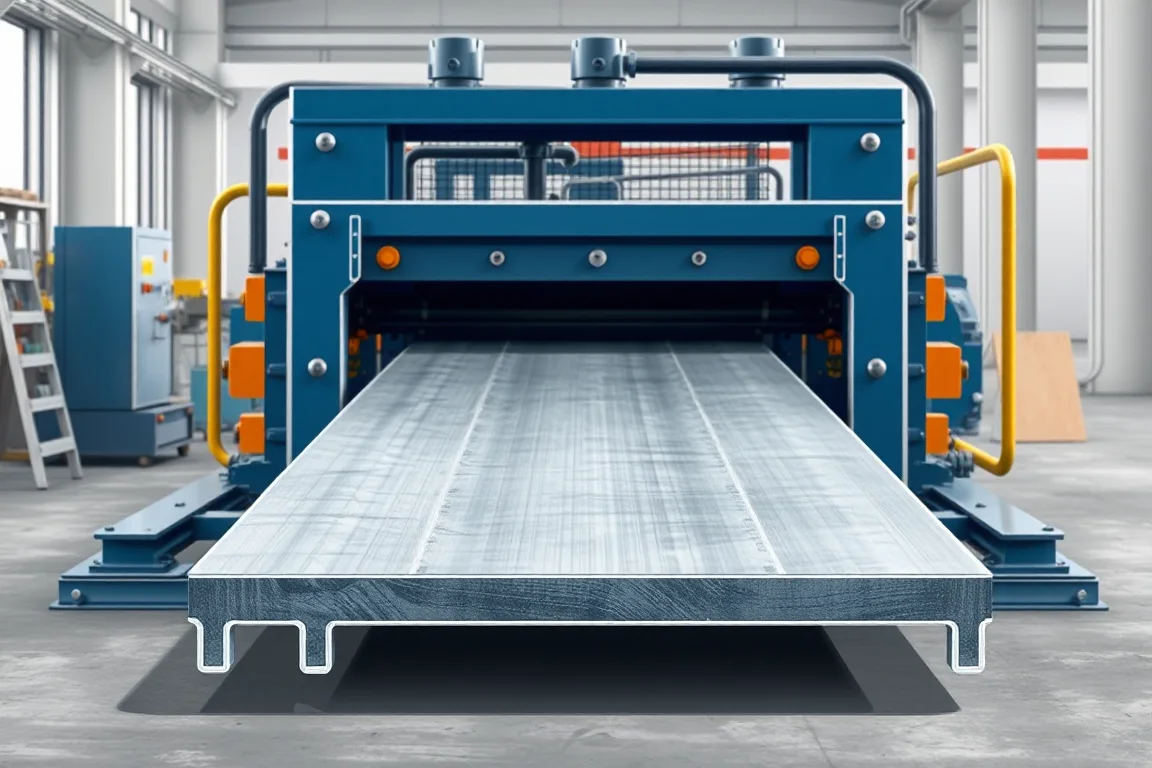
A scaffold profile roll forming line is a production system for converting flat structural steel strip into the long, shaped sections that make up a scaffold plank, toe board or deck panel. It is not a single machine category that covers every scaffold component. The finished profile, the joining method and the acceptance requirements decide whether a roll forming line is even the right production route. This article separates profile definition from forming, forming from joining, and joining from the inspection of the finished walking surface and attachment interfaces.
What the finished scaffold profile actually is
The finished article is rarely a simple channel. A scaffold plank profile typically combines a walking surface, anti-slip features, edge ribs or returns, and at least one attachment interface at each end. The ribs stiffen the section and help locate the plank on the scaffold frame. The anti-slip pattern may be punched, embossed or formed as part of the strip. Hooks, end plates and support interfaces are usually separate pieces joined to the formed body rather than features generated by the rolls alone.
Toe boards, open sections and tubes belong to different families. A toe board is a barrier, not a walking surface, so its profile and joining needs differ. An open ledger or guardrail section may be a roll formed shape or a conventional tube. A tube usually needs tube production and welded end fittings, which is a different manufacturing route. Starting from the approved scaffold-system drawing, not a generic machinery category, is what keeps these distinctions clear.
Interfaces the line must respect
Every scaffold plank has at least three interface types. The first is the walking surface, where slip resistance and surface finish matter to the user. The second is the rib or edge geometry that locates and supports the plank. The third is the end attachment, whether a hook, end plate or support bracket that mates with the scaffold frame or transom.
These interfaces do not live in the roll forming line alone. The formed body must accept the end fitting at the correct position and angle, and the joined assembly must still fit the frame. That means the drawing must define the mating features on the finished component, not only the cross-section that leaves the rolls. If the end plate is welded after forming, the weld procedure, distortion control and post-weld finish become part of the interface definition.
Material and drawing inputs
The buyer should specify structural steel grade, base-metal thickness and the required finish together. Grade affects formability, springback and weldability. Thickness affects roll load, bend radii and the stiffness of the finished plank. The finish may be mill finish, painted or galvanized, and the sequence matters. If galvanizing follows welding, the full finished component must be designed to drain and to tolerate the coating process.
The drawing should show the formed cross-section, the developed strip width, the position of any punching or embossing, the cut length, and the end-fitting details. Material and profile are not independent selections. A profile that forms well in one grade or thickness may need different roll passes or different radii in another. The operating range for thickness and grade requires supplier verification against the actual strip and profile, not an assumption carried over from a similar job.
Production route from coil to finished part
The typical route is punch or emboss, plank or channel forming, cutoff, end fitting or joining, then inspection. The sequence is deliberate. Punching or embossing before forming places the anti-slip pattern while the strip is flat and easy to locate. Forming then creates the ribs, returns and edge geometry. Cutoff separates the part at the required length. End fittings are attached in a separate operation, and inspection confirms the finished component.
Two details often decide whether the route works. First, the anti-slip pattern must be coordinated with the forming sequence. If the pattern is embossed before forming, the rolls must not flatten or distort it. If it is punched, the hole pattern must survive the bend without cracking or losing position. Second, the cutoff must be profile-supported. A cut that collapses the section or burrs the edge creates rework at the joining stage.
Tooling alternatives and what changes between them
Roll tooling for scaffold profiles generally falls into two practical alternatives. One is a dedicated set of rolls machined for a single profile and material. It offers stable forming and predictable setup, but it does not adapt to a different rib height, hook position or walking-surface width. The other is a modular or adjustable arrangement that can be reconfigured within a defined family of profiles. It can reduce the number of dedicated sets, but changeover time, setup scrap and the risk of incorrect adjustment increase.
Punching and embossing tooling follows a similar split. A dedicated punch unit places the anti-slip pattern at fixed pitch and position. An adjustable unit can change pitch or pattern width. The choice depends on how many variants the line must produce and how often. Neither alternative removes the need to verify the first-off part, because tool wear, strip camber and material batch variation all affect the result. The correct comparison is not which tooling is better in general, but which one matches the variant count, changeover frequency and inspection capability of the plant.
Cutoff, end quality and secondary operations
Cutoff determines the length of the formed body and the quality of the end that will receive the fitting. The cut should be supported by the profile so that the section does not deform. Cut length, squareness and end condition should be defined on the drawing. If the end is to be welded or bolted, the cut face and any hole pattern must suit that joining method.
Cutoff is also where secondary operations are either included or missed. Deburring, hole punching, notching for a hook or end plate, and marking may all be needed before the part is complete. A line quotation that covers only forming and cutoff leaves these operations to be arranged elsewhere. That is not automatically wrong, but the scope must be written down so the plant can plan the whole route rather than discovering the gap after installation.
Changeovers and setup discipline
Changeover is the transition between profiles, materials or cut lengths. The steps depend on the tooling alternative. A dedicated roll set may require removing and replacing roll stands or roll packs. An adjustable set may require repositioning rolls, changing punch tooling and resetting the cutoff. Either way, the changeover should be recorded as a sequence of steps with the checks that confirm each step.
Setup scrap is the material consumed before the line produces acceptable parts. It is a real cost and a real indicator of changeover quality. If the first-off part is consistently out of tolerance, the changeover procedure is incomplete or the tooling is not suited to the new profile. Recording the steps and the scrap quantity turns changeover from an operator habit into a repeatable process.
Inspection and accepted output
Inspection should cover the walking surface, the ribs and the attachment interfaces. The walking surface is checked for pattern integrity, flatness and finish. The ribs are checked for height, position and bend quality. The attachment interfaces are checked against the correct reference parts, because a formed sample alone cannot demonstrate that the finished plank will fit the scaffold frame or meet load and slip requirements. Those requirements apply to the finished component and the assembled system.
Accepted output should be defined as finished, inspected planks including end attachments. Counting only the formed body overstates the output of the line if joining and inspection are the production constraint. A high forming speed does not help if the end-fitting operation or the inspection station cannot keep up. Production target should be expressed in accepted parts per shift, with the actual profile and material, not as a single number that ignores the rest of the route.
Comparing a full line with a partial scope
A full production scope includes forming, punching or embossing, cutoff, end-fitting equipment, joining fixtures, handling and verification. A partial scope includes only some of these, with the remainder supplied or performed separately. The full scope gives a single route and a single point of responsibility for the finished component. The partial scope can be appropriate when the plant already has welding, coating or inspection capability, or when the end fittings are bought in.
The practical comparison should be made on the finished part, not on the forming machine alone. Ask what operations are needed to convert the formed body into an accepted scaffold plank, and compare that list with the equipment scope. If the scope omits joining or inspection, the quotation is not comparable to a full-line offer. If it includes them, the changeover, tooling and inspection requirements should be described alongside the forming section.
Practical checklist before approving a line
- Confirm that the approved scaffold-system drawing defines the formed section, the end fitting and the mating interfaces.
- State the steel grade, base-metal thickness, finish and joining procedure as one material specification.
- Decide whether galvanizing or painting follows or precedes welding, and include the full finished component in that decision.
- Run the agreed material and profile, not an easier demonstration substitute.
- Inspect first-off pieces and a representative steady-production sample with the agreed gauges.
- Record changeover steps, setup scrap, punching time and unloading time.
- Compare the written equipment scope with every secondary operation needed for a finished part.
- Define accepted output per shift using the actual profile and material.
- Confirm the electrical supply, voltage, frequency and phase, and require a confirmed equipment schedule for installed power.
Frequently asked questions
Can one scaffold profile roll forming line make planks, toe boards and tubes?
It can make the roll formed sections within a defined profile family, but planks, toe boards and tubes have different functions and joining requirements. A tube usually needs tube production and welded end fittings rather than the same roll forming route. Grouping them into one machinery category hides those differences. The line should be specified against the drawings it will actually produce.
Where should anti-slip punching or embossing be placed in the line?
It should be coordinated with the forming sequence. Placing the pattern while the strip is flat gives stable location, but the rolls must not flatten or distort it. The correct position depends on the pattern type, the rib geometry and the material. The first-off part should confirm both pattern integrity and final position after forming.
What does a profile-supported cutoff change?
It supports the section during cutting so the profile does not collapse and the end condition suits the joining method. It also helps control cut length and squareness. The cutoff requirement should be written against the drawing and the end fitting, not treated as a generic saw or shear choice.
How should production target be defined for a scaffold profile line?
It should be defined as accepted, inspected planks including end attachments, per shift, using the actual profile and material. A forming speed alone does not describe the output of the line because joining and inspection may be the constraint. Defining the full route makes the target meaningful.
Why can a formed sample not prove load or slip performance?
Load and slip requirements apply to the finished component and the assembled scaffold system. A formed sample does not include the end fitting, the joining method or the interface with the frame. Those are part of the finished article and must be assessed on the completed component, not inferred from the formed body.
What should be recorded when the material or tooling changes?
Record the change against the component definition, including the profile, grade, thickness, tooling set and joining process. Then inspect the first-off part and a steady-production sample with the agreed gauges. This keeps the change traceable to the approved drawing and to the acceptance requirements for the scaffold system.

Continue your research
- Scaffolding Roll Forming Machines
- Scaffold Plank Roll Forming Machine
- Scaffolding Deck Roll Forming Machine
- Ringlock Scaffold Ledger Roll Forming Machine
- Cuplock Scaffold Ledger Roll Forming Machine
- Scaffold Frame Profile Roll Forming Machine
- How Scaffolding roll forming machine Works
- How To Choose a Scaffolding roll forming machine
- Scaffolding roll forming machine Price: What Affects the Cost?
Configuration & specification inputs
Match the configuration to your section drawing, material and production requirements.
| Parameter | Requirement / confirmation needed |
|---|---|
| Profile geometry | A scaffold-profile project should distinguish planks, toe boards, open sections and tubes. Grouping all of them into one machinery category obscures the different joining and verification requirements. |
| Material | Specified structural steel with the required finish and joining procedure |
| Thickness & grade | Buyer to specify base-metal thickness and grade; operating range requires supplier verification. |
| Process route | Punch/emboss → plank or channel forming → cutoff → end fitting/joining → inspection |
| Cutting | Confirm profile-supported cutoff, cut lengths, end quality and any secondary operations. |
| Output | Define accepted output per shift with the actual profile and material. |
| Electrical supply | Buyer to state voltage / frequency / phase. Installed power requires a confirmed equipment schedule. |
| Acceptance | Use the approved drawings and acceptance requirements for the intended scaffold system. Inspect mating interfaces with the correct reference parts. Record changes to material, tools or joining processes against those component definitions. |