
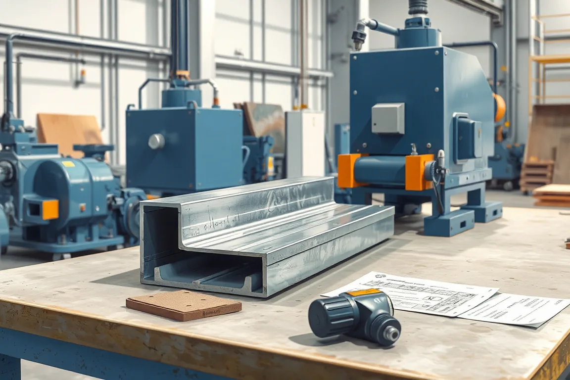
A scaffolding roll forming machine is not a single product category. It is a production line built around one family of sheet-steel components: planks with anti-slip surfaces and ribs, toe boards, and certain open or channel sections. Ledgers and standards in many scaffold systems are tubes with welded end fittings, so they belong to tube production rather than sheet-profile roll forming. The practical starting point is therefore the approved scaffold-system drawing: the connection method, the component function and the finished-part definition decide which process route is relevant.
Start From the Approved Scaffold-System Drawing
A scaffold plank, a toe board and a ledger perform different jobs. A plank carries foot traffic and needs a walking surface, side ribs and end details that locate it on the system. A toe board is a simpler edge-retention section. A ledger forms the horizontal connection between standards, and in many systems it is a tube with welded or forged ends. If the drawing calls for a tubular member, a sheet-profile roll former is the wrong route regardless of how capable the machine is. Before comparing machines, confirm whether each part is an open sheet section or a tube, and which connection system it serves. Ringlock and cuplock describe connection systems; they do not by themselves prove that a ledger is made on a sheet-profile line.
Map the Full Process Chain Before the Machine
Roll forming is one stage inside a longer sequence. A typical plank route begins with decoiling and feeding, then punching or embossing for the anti-slip pattern, then progressive forming of the plank or channel profile, then cutoff, and finally end fitting, joining and inspection. Each arrow in that sequence is a hand-off where tolerances, orientation and part tracking matter. Punching before forming means the holes travel through the rolls and can distort; punching after forming avoids that but usually needs a separate press and a transfer. Embossing an anti-slip texture is a forming operation in its own right and has to be coordinated with the roll stands so the pattern is not flattened later. End hooks, end plates and support interfaces may need separate manufacturing and joining equipment: presses, welding, riveting or fastening stations. If production depends on equipment outside the roll former quote, that equipment belongs in the same comparison, because the line does not produce accepted planks without it.
Define Material and Thickness as a Verified Envelope
Structural steel grade and base-metal thickness are buyer inputs, not machine claims. The machine's operating range must be verified by the supplier against the specific grade and thickness, because yield strength, elongation and coating affect roll loads, springback and edge quality. A quoted range for one steel type does not transfer automatically to a higher-strength or coated grade. The editorial scope here is the decision method, not a capacity figure: state the material and thickness envelope in writing, ask how it was confirmed, and separate a demonstrated capability from a proposed future option. If the answer is that a heavier gauge requires additional stands or a different drive, that is a legitimate engineering boundary, not a defect.
Anti-Slip Punching and Embossing in the Forming Sequence
Anti-slip treatment is the feature that most distinguishes a plank line from a general profile line. Punching produces discrete raised or displaced features; embossing deforms the surface into a texture. Both interact with the forming sequence. Punched holes can act as stress concentrators and can open or close as the strip passes through later stands. Embossed texture can be ironed out if the rolls after the embossing station contact the same surface. The decision is where in the sequence the pattern is created and how it is preserved. Ask for the station order, which rolls touch the walking surface after embossing, and how the pattern depth and coverage are checked at the end of the line. Those are inspection questions, not performance claims: the walking-surface requirement belongs to the finished component and the assembled system.
Cutoff, Cut Length and End Quality
Cutoff sits at the end of the forming line and has to suit the formed section. A profile-supported cutoff uses tooling shaped to the section so the cut does not crush or twist the part. The decision points are: which profiles the cutoff tooling supports, what cut lengths and length tolerance the line can hold, and what the cut end looks like before any secondary operation. Some sections need a shear cut; others need a die cut or a saw. If the end is subsequently joined to a plate or hook, the cut end quality affects fit-up and the joining process. A flying cutoff allows continuous production; a stationary cutoff stops the line for each cut. The right choice depends on the product mix and on how much secondary work each end needs.
Separate Component Production From Joining and Certification
Roll forming produces a formed component, not a certified scaffold part. Joining end fittings, welding hooks or plates, applying finish, and any load or slip qualification belong to separate stages. Inspection of the walking surface, ribs and attachment interfaces can be done at the line, but load and slip requirements apply to the finished component and the assembled system, and cannot be inferred from a formed sample. Keep three columns in mind: what the roll former produces, what joining and finishing equipment produces, and what testing and certification confirm. A quote that covers only the first column is incomplete for a scaffold component.
How To Compare Machine Configurations
Compare configurations on the same drawing revision and material envelope. A single-profile line with fixed stands is simpler and cheaper to run but locks the product mix. A line with adjustable or interchangeable stands handles more profiles but adds changeover time and setup skill. A line with inline punching and embossing reduces handling but makes the station order and tooling more complex. A line with a separate press and transfer is easier to change but adds labor and floor space. None of these is universally better; the trade-off is changeover flexibility against capital and complexity. Ask for a changeover demonstration for the intended product mix rather than a catalog statement, and define what the demonstration must show: profile dimensions, pattern quality, cut end condition and part-to-part consistency.
What a Meaningful Demonstration Looks Like
A useful demonstration runs the actual material grade and thickness and the actual section family. It should show the full sequence from feed through cutoff, including any inline punching or embossing, and it should produce enough parts to reveal drift. Inspect the walking surface, the ribs and the attachment interfaces on the produced parts. Measure the same features the drawing controls: profile dimensions, pattern position and depth, hole position, cut length and end squareness. Record the operating conditions and any manual adjustments made during the run, because a line that needs constant intervention behaves differently in production. A demonstration proves that the sequence can produce the shape; it does not prove the finished component's load or slip behavior.
Power, Utilities and Site Fit
Voltage, frequency and phase are buyer inputs. The installed power requirement comes from a confirmed equipment schedule that includes the roll former, punching or embossing press, cutoff, decoiler, and any joining equipment. Floor space, foundation loading, coil handling, and dust or scrap extraction also affect site fit. Treat the utility list as part of the quote scope: if the schedule omits the press or the welder, the line cannot reach accepted output as quoted.
Cost and Quote Scope: Reading the Same Line Twice
Two quotes for the same nominal line can differ because they cover different scopes. A meaningful comparison separates what is required, what is included and what is excluded. Typical excluded items include the decoiler, the punching or embossing station, the cutoff tooling for additional profiles, the joining equipment, the finish line, and the acceptance measurement plan. The cost that matters is not the line price alone but the cost per accepted finished component: material yield, scrap rate at startup and changeover, labor for secondary operations, and the inspection effort needed to hold the drawing. Because prices depend on scope, material and tooling count, a responsible comparison normalizes all quotes to the same drawing revision, the same material envelope and the same finished-part definition. Ask each supplier to answer against that same revision and to mark confirmed capability separately from proposed options.
Decision Checklist
- Confirm from the system drawing whether each part is an open sheet section or a tube.
- Write the material grade and thickness envelope as a buyer input, and ask how the supplier verified it.
- List the full sequence: feed, punching or embossing, forming, cutoff, joining, finish, inspection.
- Identify which profiles the cutoff tooling supports and what secondary operations follow.
- Include outside equipment in the comparison if production depends on it.
- Request a changeover demonstration for the intended product mix.
- Agree acceptance measurements before committing to tooling.
- Build a required, included and excluded comparison against one drawing revision.
Frequently Asked Questions
Can one scaffolding roll forming machine make planks, toe boards and ledgers?
Planks and toe boards are open sheet sections that can share a roll forming route if the profile families and material envelopes are compatible. A conventional tubular ledger usually needs tube production and welded end fittings instead, so it belongs to a different process chain. Confirm tube or open-section construction from the system drawing before assuming one line covers all three.
Should anti-slip punching happen before or after forming?
It depends on how the pattern must be preserved. Punching or embossing before forming lets holes and texture travel through the rolls, which can distort them; doing it after forming protects the pattern but needs a separate station and transfer. The deciding evidence is the station order and which rolls touch the walking surface afterward. Ask how pattern depth and coverage are checked at the end of the line.
Does the quoted machine range prove it can run my steel grade?
No. A range quoted for one grade or thickness does not transfer automatically to a different grade, coating or thickness, because roll loads, springback and edge quality change. Treat the operating range as verified only when the supplier confirms it against your stated material and thickness. A requirement that heavier gauge needs more stands or a different drive is a normal engineering boundary.
What does a formed sample prove about the finished plank?
It proves the sequence can produce the intended shape and pattern within the measured tolerances. It does not prove the load or slip behavior of the finished component or the assembled system. Those requirements apply to the joined, finished part and the system as a whole, so plan separate load and slip qualification rather than inferring performance from a formed sample.
Why do two quotes for the same line look different?
Because they usually cover different scopes. One may include the decoiler, inline punching and cutoff tooling; another may exclude them and price only the forming section. Normalize every quote to the same drawing revision, material envelope and finished-part definition, then mark required, included and excluded items. The useful figure is cost per accepted finished component, not the line price alone.
How should I judge changeover capability?
Judge it against your actual product mix, not a general claim. Ask for a changeover demonstration that shows the profiles, the setup time, the adjustments required and the part quality after the change. Record any manual intervention during the run, because a line that needs constant adjustment behaves differently in production than in a controlled demonstration.
Continue your research
- Scaffolding Roll Forming Machines
- Scaffold Plank Roll Forming Machine
- Scaffolding Deck Roll Forming Machine
- Ringlock Scaffold Ledger Roll Forming Machine
- Cuplock Scaffold Ledger Roll Forming Machine
- Scaffold Frame Profile Roll Forming Machine
- How Scaffolding roll forming machine Works
- Scaffolding roll forming machine Price: What Affects the Cost?
- Materials and Thickness for Scaffolding roll forming machine