ROLL FORMING SYSTEMS / PROFILE-LED SELECTIONFROM COIL TO FINISHED COMPONENT · EN
ROLLVANTAROLL FORMING SYSTEMS

APPLICATIONS / FROM PROFILE TO PROCESS

Profiles & Applications

Explore named profiles and production variants through geometry, mating interfaces, material combinations and manufacturing requirements.

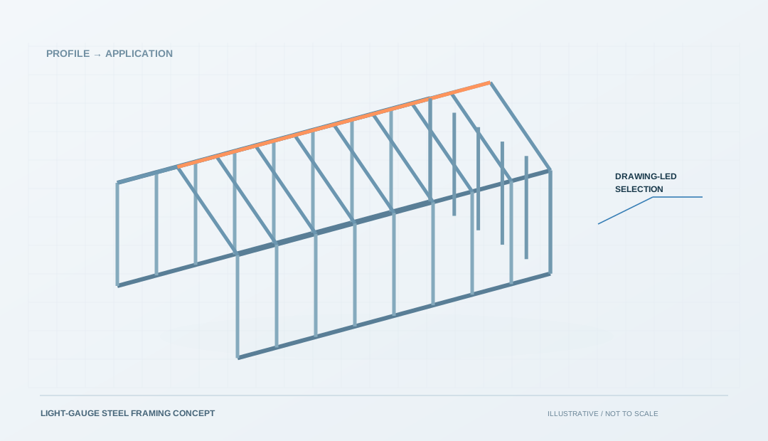
Drawing and production planning illustration

01 / Define the componentGeometry, interfaces and finished-part requirements

02 / Understand the processMaterial, tooling, forming and secondary operations

03 / Compare the complete scopeAccepted output, changeover and inspection

APPLICATIONS / FROM PROFILE TO PROCESS

Find your finished component

Explore each topic in detail. The collection below uses the current published content.

ROLLVANTA / EXPLORE

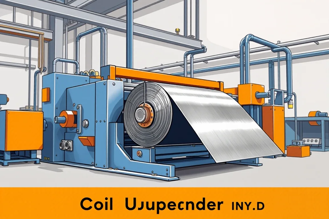
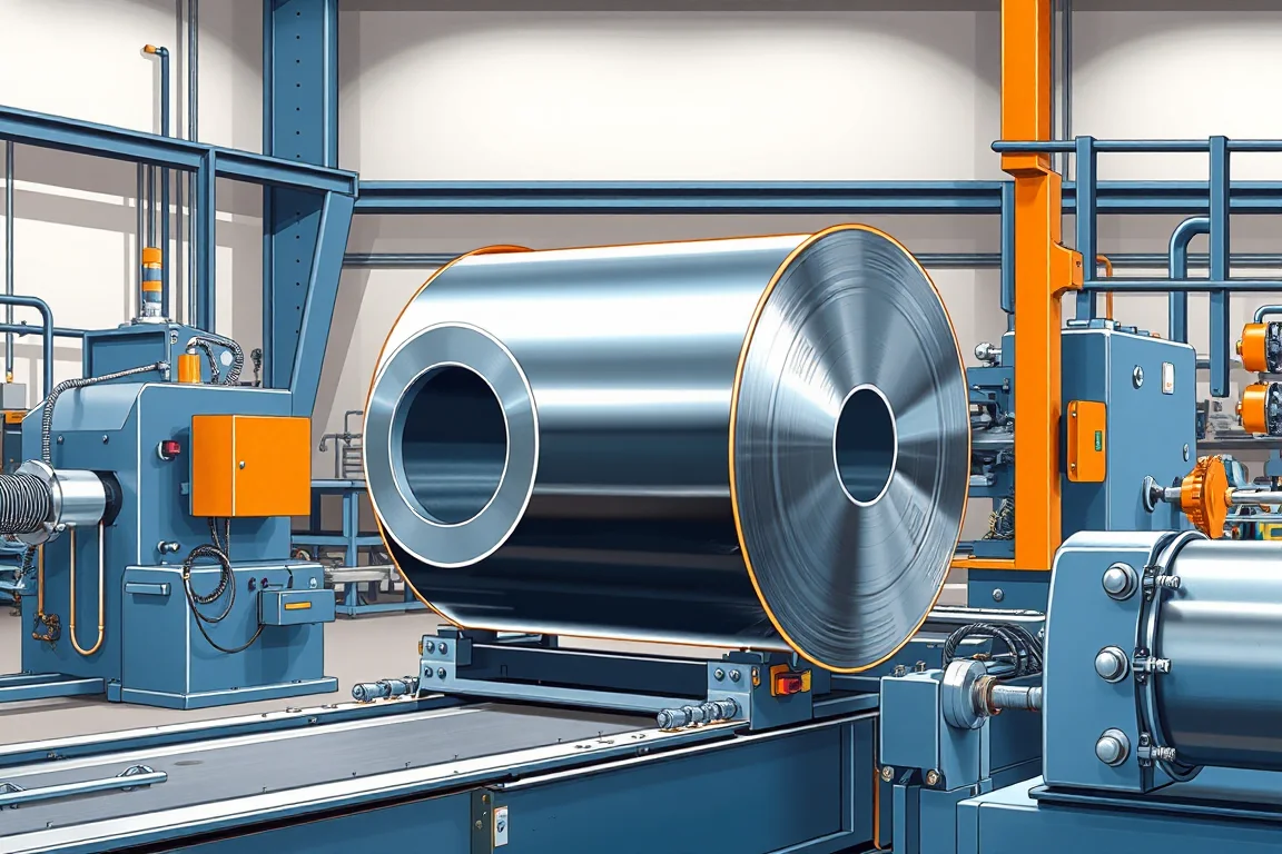
Coil Upender Machine

A coil upender changes coil orientation as material-handling equipment. This profile explains interfaces, restraint, production routes, inspection boundaries, a practical checklist and FAQs for specifying orientation change without confusing it with slitting, leveling or forming functions.

Explore the details

ROLLVANTA / EXPLORE

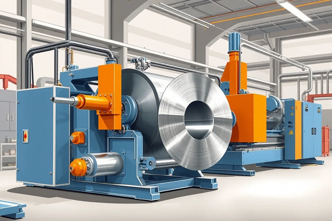
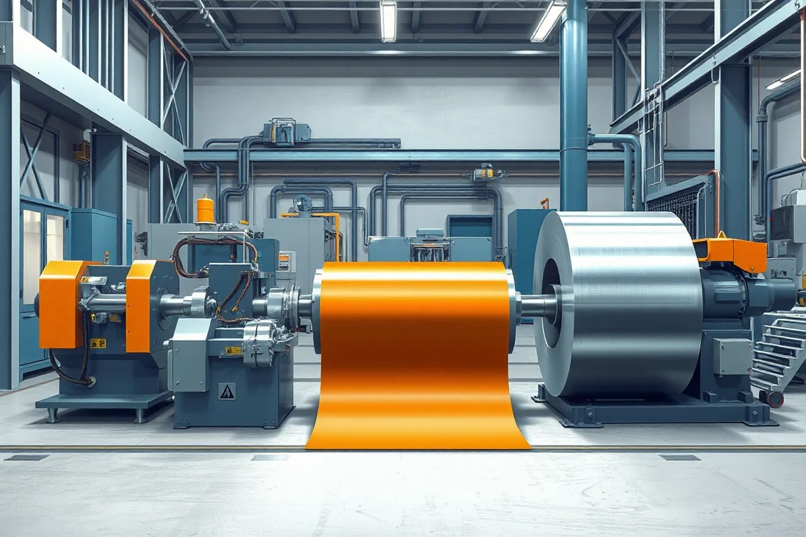
Decoiler Straightener Feeder Line

A decoiler straightener feeder line integrates coil payoff, strip leveling, and controlled feed into a downstream press or process. This profile explains component interfaces, route choices, assembly boundaries, and application-specific inspection without inventing machine ratings.

Explore the details

ROLLVANTA / EXPLORE

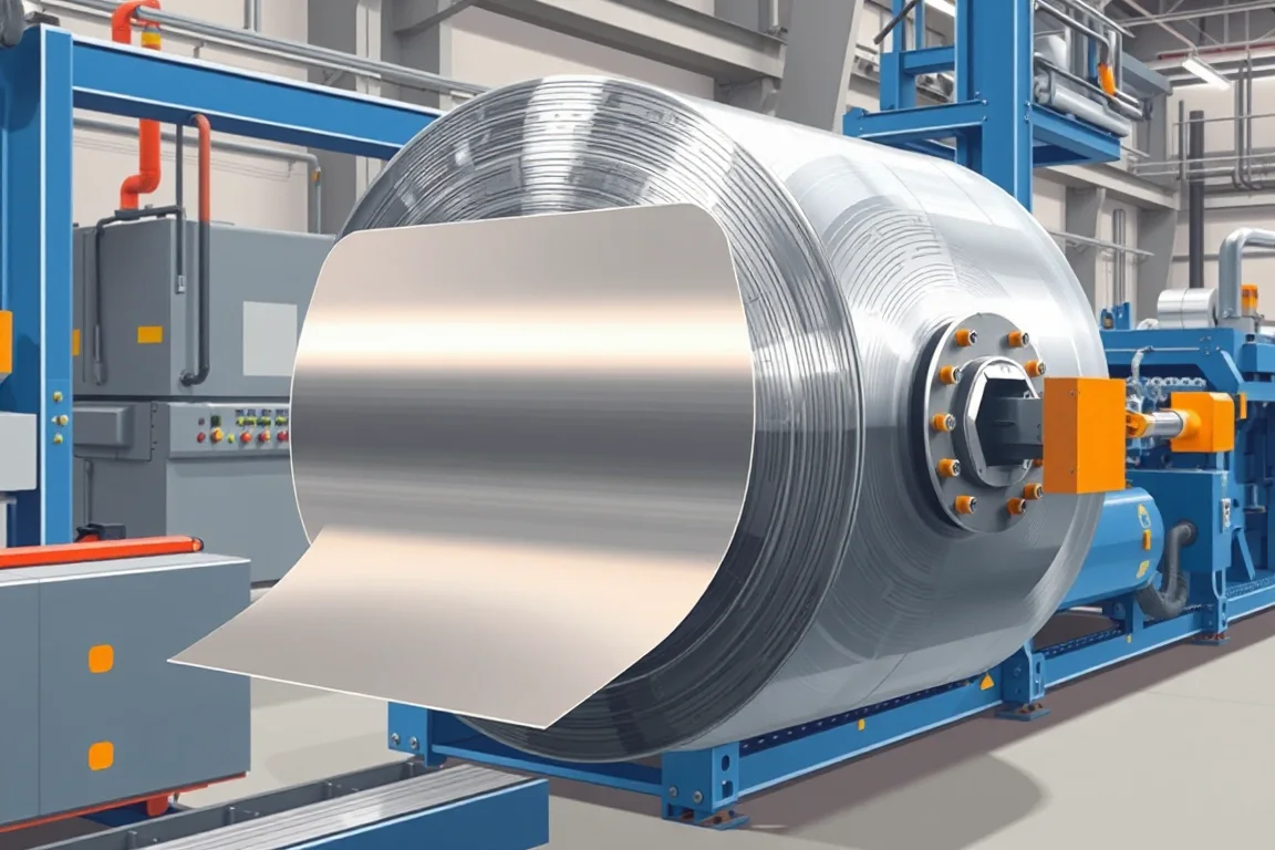
Steel Coil Blanking Line

A steel coil blanking line transforms coiled strip into flat rectangular or shaped blanks. This guide clarifies component interfaces, production routes, inspection points, and practical selection criteria to match equipment with your specific blank geometry and material.

Explore the details

ROLLVANTA / EXPLORE

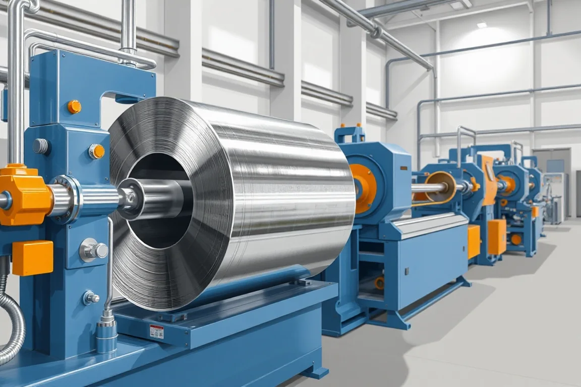
Heavy Gauge Steel Coil Slitting Line

A heavy gauge steel coil slitting line turns wide, thick coil into narrower strips using paired thickness-and-strength capacity, defined knife setup, scrap handling and recoiling. This profile explains component interfaces, route boundaries, inspection and scope items to assess.

Explore the details

ROLLVANTA / EXPLORE

High Speed Steel Coil Slitting Line

A high speed steel coil slitting line converts wide coils into narrower strips at defined rates. Success depends on matching coil data, slit pattern, tension and recoiling quality, not on peak speed. This profile explains interfaces, production routes, inspection and quotation scope.

Explore the details

ROLLVANTA / EXPLORE

Narrow Strip Steel Coil Slitting Line

Narrow strip steel coil slitting lines convert wide coils into multiple precise strands. This profile explains interfaces, production routes, assembly boundaries, and application-specific inspection for reliable narrow strip output.

Explore the details

ROLLVANTA / EXPLORE

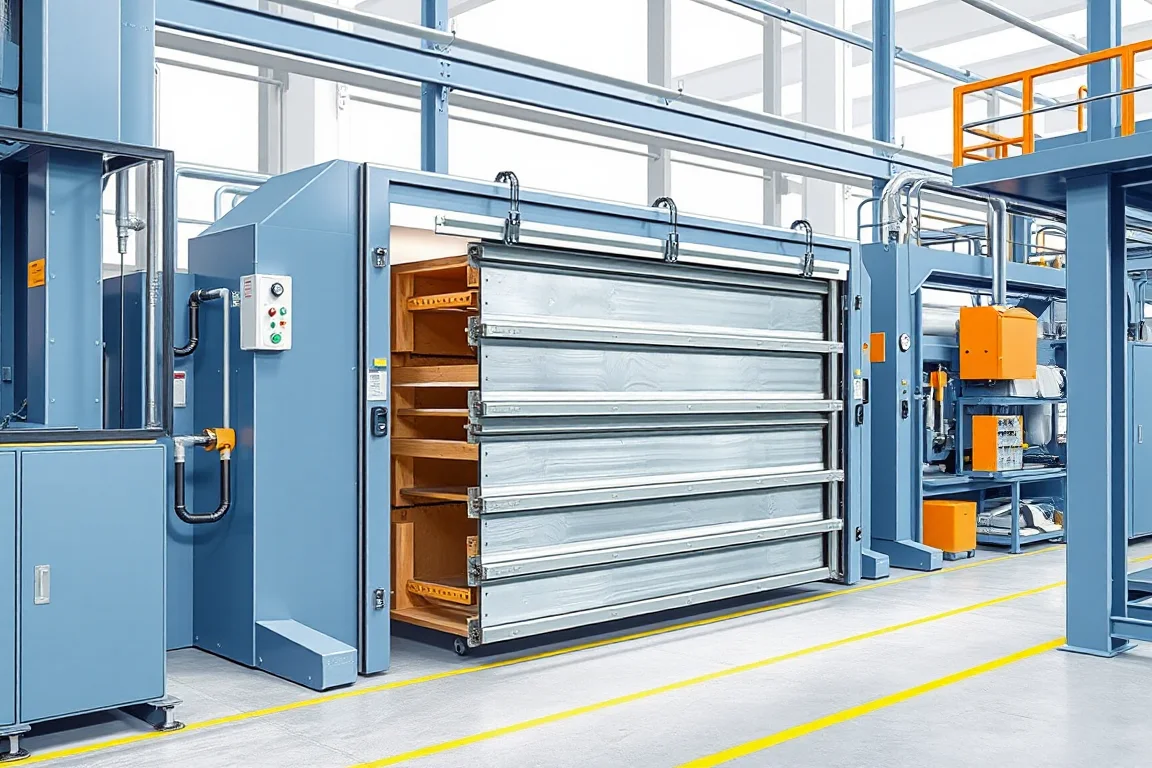
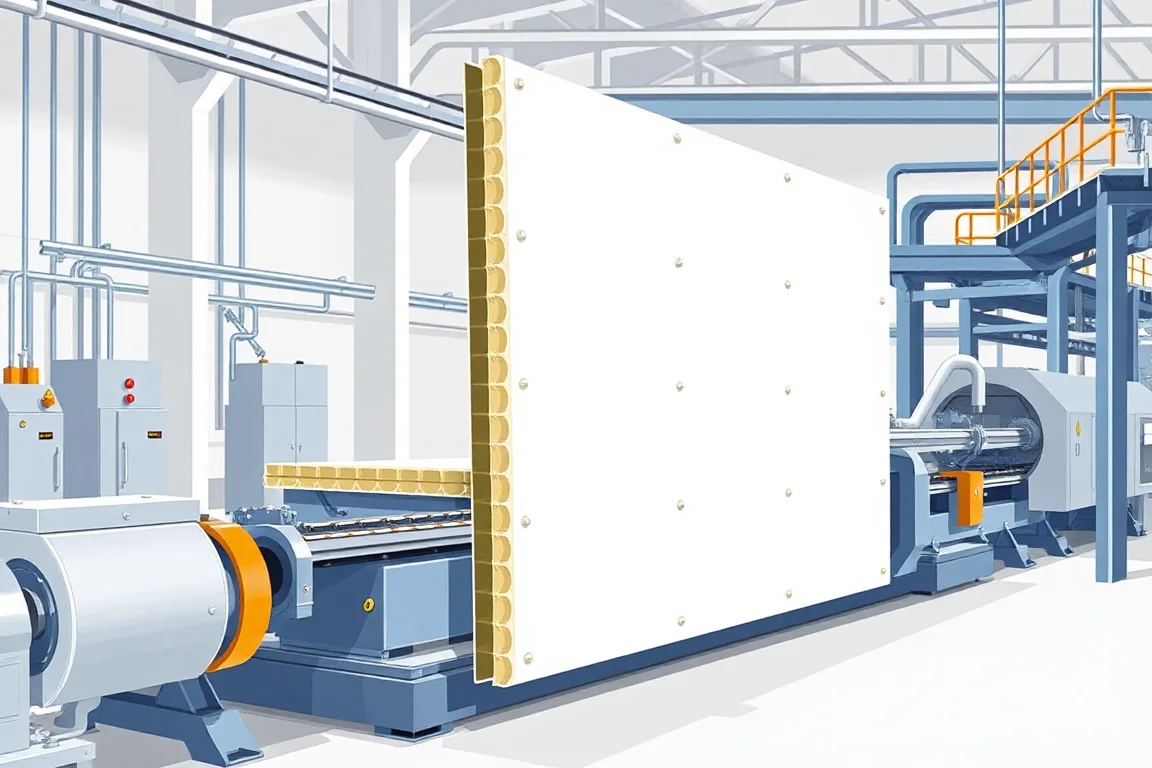
Garage Door Sandwich Panel Production Line

Garage door sandwich panels must articulate as part of a finished door, so production involves more than bonding facings to a core. This article explains the specific panel interfaces, process routes, cutoff considerations and application-focused inspection needed to assess a garage door sandwich panel production line.

Explore the details

ROLLVANTA / EXPLORE

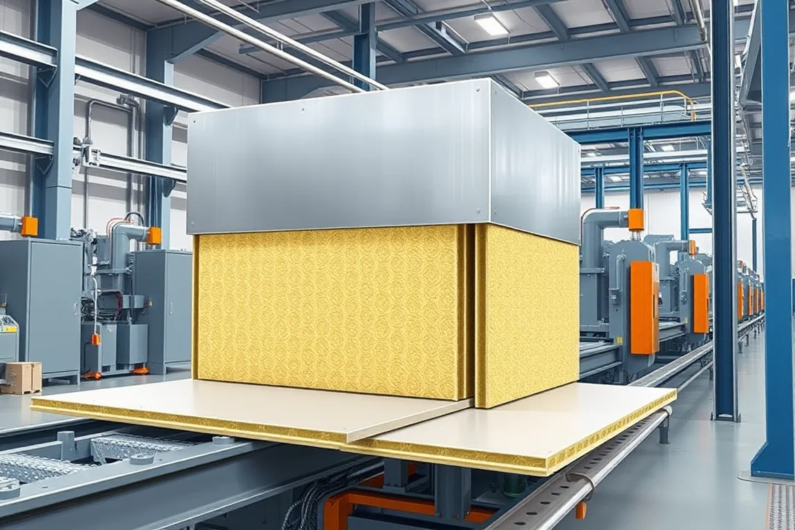
Cold Room Sandwich Panel Production Line

A cold-room sandwich panel line must deliver panels whose joint, seal and vapor-control strategy matches the finished cold-room system. This guide separates appropriate production routes, assembly boundaries and inspection so buyers can specify equipment without treating the line as a verified assembly rating.

Explore the details

ROLLVANTA / EXPLORE

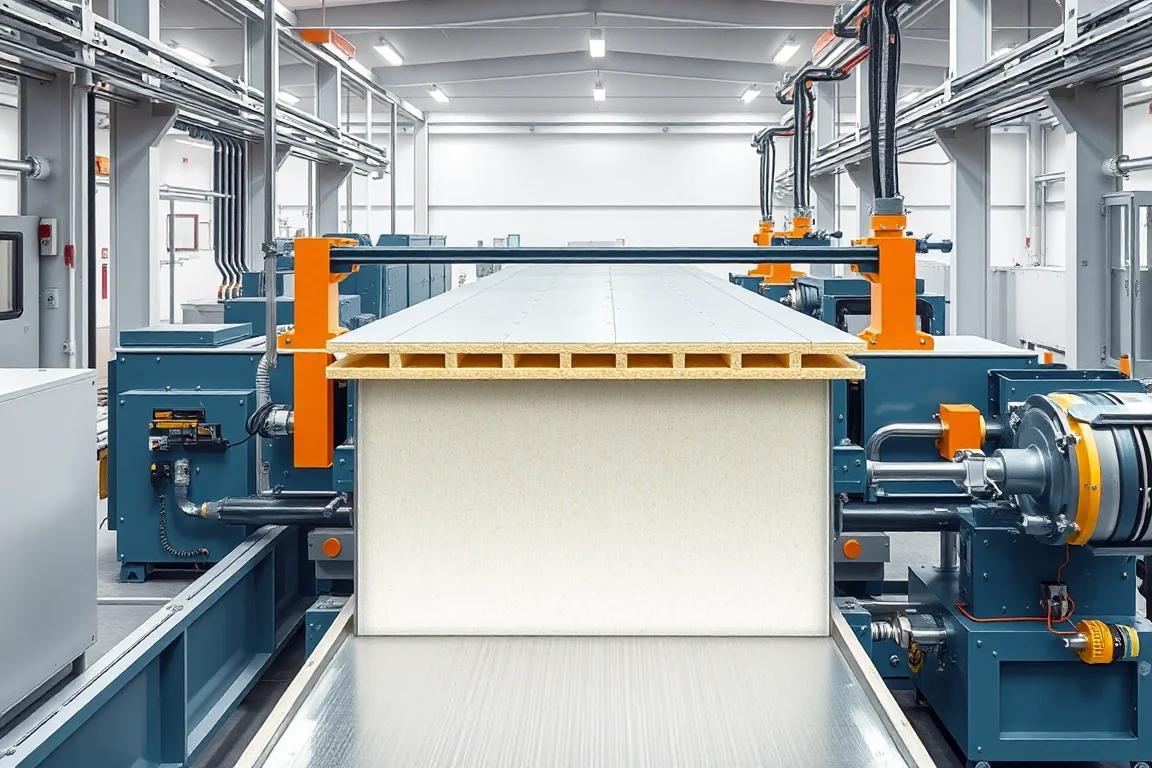
PU PIR Sandwich Panel Production Line

Understand how a PU PIR sandwich panel production line works, where component boundaries fall between facing preparation, foam dispensing, pressing, curing and cutoff, and how to specify and verify output for your exact panel.

Explore the details

Find the production questions behind a particular profile, size family or manufacturing arrangement. Application names are a starting point: a complete drawing must still identify the geometry, mating parts, material and features that make the finished component useful.

Read profile names as a starting point

A nominal cover width, section depth or seam height does not describe every bend and interface. Compare the rib or flange pattern, returns, radii, laps and feature locations. Where a new part must match an existing system, include a reference sample or controlled mating drawing.

Distinguish shape from production method

Some applications concern a joint or finished section; others concern tapering, curving, variable sizes or rapid changeover. Identify which requirement changes the tooling and which introduces another process. This avoids assuming that a standard forming line includes a specialized downstream operation.

Pair the material with the geometry

Review the actual combinations of grade or alloy, base-metal thickness, coating and dimensions. Separate demonstrations at unrelated limits do not prove that every possible combination has been covered. A compact production matrix makes the important trial cases visible.

The application pages explain the local requirements; the machine directory shows the broader equipment family. Follow with the technical guides when you need a method for comparing output, preparing an enquiry or agreeing acceptance checks.

Turn research into a practical brief

Bring your profile.
Clarify your production line.

Organize the drawing, material, product mix and acceptance questions before comparing configurations.

Build a project brief →