
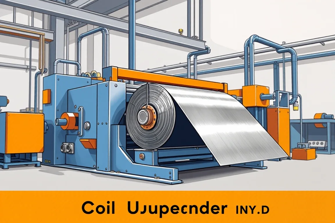
A coil upender machine rotates a wound coil between two handling orientations, most commonly from eye-to-sky (axis vertical) to eye-to-horizontal (axis horizontal) or the reverse. Its purpose is to present the coil correctly to the next operation, such as a decoiler, a slitting line, a cut-to-length line or a storage saddle. It does not slit, level, edge-trim, blank or form strip. Treating it as a processing machine rather than material-handling equipment leads to the wrong acceptance criteria, the wrong safety discussion and a quotation that omits the very interfaces that determine whether the coil actually reaches the line.
What orientation change does and why it matters
Coil orientation determines how the coil can be lifted, stored and threaded. A coil standing on its edge can be placed on a saddle with its eye horizontal for payoff into a line. A coil lying flat can be stacked or moved through a warehouse differently. The upender performs only that rotation. The value it adds is interface value: it converts the coil from the orientation delivered by the mill or the crane to the orientation demanded by the receiver process. When that interface is wrong, operators improvise with slings, blocking or extra handling, which is where damage and incidents tend to occur.
Material and geometry inputs that define the duty
The starting information is not a single rating but a coil envelope. Width, thickness, mass, inside diameter and outside diameter together describe what the machine must support and contain. Two coils of the same mass can behave differently if one is narrow and thick and the other wide and thin, because the footprint on the cradle and the tendency to telescope or sag differ. Grade and strength matter because harder material resists deformation but also stores more energy if a wrap separates. Surface condition matters because contact surfaces, cradle lining and restraint method may need to be chosen so that marking or scratching is avoided on visible or coated faces.
Component interfaces on the upender itself
An upender is a system of interfaces. The load-carrying interface is the cradle or table that contacts the coil. The rotating interface is the pivot, drive or powered arc that performs the orientation change. The restraint interface is what keeps the coil from shifting, rolling or sliding during rotation. The foundation or floor interface transfers load and reaction. The control interface governs start, stop, position and any interlocks. Each of these can be designed differently, and each changes what the operator must do before, during and after a lift.
Restraint is the deciding safety feature
Orientation change moves a heavy wound mass through an arc. Restraint should be understood as preventing movement relative to the cradle, not merely holding the coil in place at rest. The method may involve a mandrel, side guides, a clamp, a retaining arm, chocks or a combination. The appropriate choice depends on coil geometry, mass distribution and whether the coil is loose-wound, tightly wound, banded or unwrapped. A restraint concept that works for a tight, banded coil may be unsuitable for a coil whose outer wraps can shift. Operators need a defined sequence for securing the coil before rotation begins.
Production routes: standalone handling versus line integration
An upender can be purchased and used as a standalone handling device, or it can be integrated into a production route such as coil loading, payoff, leveling or slitting, length control or recoiling, and then handling again. Standalone use puts the interface burden on cranes, forklifts, saddles and the next machine. Integration moves the interface into the line layout, where the upender position, discharge height, control handshake and operator access must be coordinated with the neighboring equipment. Neither route is automatically better. The standalone route can be simpler and easier to relocate. The integrated route can reduce double handling but requires layout and control coordination that must be defined before quotation.
Assembly boundaries and quotation scope
It is useful to separate three things that are often blended in a single price: the upender machine, the handling equipment around it, and the installation and commissioning work. The upender machine may include the structure, drive, cradle, restraint and local controls. Handling equipment may include coil cars, cranes, saddles, conveyors, turning rolls or transfer tables. Installation includes foundations, anchoring, power connection and alignment. A quotation that covers only the rotating unit but not the transfer that feeds or receives it can look complete while leaving the real production cycle undefined. Ask for a written scope that names each item and states who supplies it.
How to compare upender alternatives
Alternatives differ in how they perform the rotation and how they restrain the coil. A powered rotating cradle may suit frequent, repetitive orientation changes. A pivot or tilting table may suit a narrower range of coil sizes. A lifting-based method using a C-hook or specialized spreader may be preferred when the coil must also be transported. A coil car with a rotating deck may combine transport and orientation. Comparing them requires matching the actual coil envelope, the available floor space, the lifting equipment already present, the required throughput and the operator exposure during rotation. A method that reduces handling steps but increases exposure is not automatically preferable.
Inspection and acceptance at the handling boundary
Acceptance for an upender is different from acceptance for a slitting or cut-to-length line. It centers on the ability to change orientation safely and repeatedly without damaging the coil or the machine. Useful checks include verifying that the coil is fully seated before rotation, that restraint engages as intended, that rotation completes without abnormal movement, that the discharge position matches the receiving equipment, and that the operator can remain outside the movement envelope. The approved operating procedure should be used, not improvised trials with unsecured loads. For lines, material acceptance for width, edge burr and recoiling quality applies to slitting, while length, squareness and flatness apply to cut-to-length; those are separate from the upender check.
Practical checklist before approving an upender
- Define the full coil envelope: width, thickness, mass, inside diameter and outside diameter, with grade and surface condition.
- State the required start and finish orientations and the equipment that will receive the coil.
- Confirm how the coil is restrained before rotation and how that restraint is released.
- Map the full handling route: how the coil arrives, how it is loaded, how it is discharged, and what moves it next.
- Identify adjacent lifting equipment and whether it is in scope or excluded.
- Define the operator exclusion area and how it is enforced during rotation.
- Obtain a capacity and safety review for the actual coil envelope, not a simplified demonstration case.
- Confirm the power supply characteristics the buyer will provide and the equipment schedule the supplier will deliver.
- Agree the acceptance procedure in writing, including who performs it and what records are kept.
- Check that the written scope includes every transfer, saddle, control interface and installation task needed for the first production coil.
Common specification mistakes
One recurring mistake is specifying an upender by a single maximum mass figure and treating that as the whole requirement. Coil outside diameter and width affect stability during rotation, and inside diameter affects whether a mandrel-based restraint is even possible. Another mistake is omitting the receiving equipment from the layout, so the upender discharges into a position the decoiler or saddle cannot accept. A third is assuming that a machine rated for one coil family will handle another with a different wrap condition or surface requirement. A fourth is leaving the operator procedure undefined, which pushes risk onto the floor. Each of these can be resolved by describing the coil envelope, the route and the interfaces rather than shopping on one number.
Where the upender fits relative to neighboring lines
An upender is not a narrow strip steel coil slitting line, a high speed slitting line, a heavy gauge slitting line, a steel coil blanking line or a decoiler straightener feeder line. Those systems perform processing functions such as slitting, blanking, leveling and feeding. The upender only changes orientation and presents the coil. If a project needs narrower strip, cut sheets, improved flatness or controlled payoff, those requirements belong to the processing equipment, and the upender should be specified to match what that equipment expects at its entry or exit. Keeping the boundary clear prevents the upender from being asked to solve a processing problem it cannot address.
FAQ
Does a coil upender level or flatten the coil?
No. Leveling changes flatness through roll arrangements in a separate machine. An upender rotates the coil and does not alter strip flatness, thickness or internal stress. If flatness is a requirement, it must be addressed by leveling equipment and verified with agreed flatness checks.
Can one upender handle both eye-to-sky and eye-to-horizontal coils?
Many upenders are intended to rotate between two defined orientations, but whether a specific unit can handle both directions depends on its design, drive, restraint and the coil envelope. The requirement should be stated as a defined start orientation and finish orientation for the actual coils, and the machine concept should be reviewed against that, not against a generic description.
Why is restraint more important than rotation speed?
Restraint prevents the coil from shifting relative to the cradle while it moves through an arc. A rapid rotation with inadequate restraint is not a productivity advantage; it is an uncontrolled load. Speed matters for cycle time, but restraint and sequence determine whether the orientation change is controlled and repeatable.
What determines the production route around an upender?
The route is determined by how the coil arrives, what orientation the receiving process needs, what equipment moves the coil between steps, and how much double handling is acceptable. A route that minimizes lifts may be preferable even if it requires more layout coordination. The route should be drawn before the upender is selected.
How should acceptance checks differ from a processing line?
Acceptance at the upender centers on safe orientation change, correct discharge position and no coil damage. Acceptance for slitting and cut-to-length lines addresses width, edge burr, recoiling, length, squareness and flatness. The two sets of checks should be kept separate so that an upender is not judged on processing outputs it does not produce.
Is an upender required if a rotating coil car is already available?
Not necessarily. A rotating coil car may perform both transport and orientation change, which can reduce handling steps. Whether it replaces a dedicated upender depends on the required orientations, the coil envelope, the layout and the control integration. The comparison should be made on the full handling cycle, not on the function name alone.

Continue your research
- Coil Processing & Auxiliary Equipment
- Steel Coil Slitting Line
- Cut To Length Line
- Narrow Strip Steel Coil Slitting Line
- High Speed Steel Coil Slitting Line
- Heavy Gauge Steel Coil Slitting Line
- How Coil processing line Works
- How To Choose a Coil processing line
- Coil processing line Price: What Affects the Cost?
Configuration & specification inputs
Match the configuration to your section drawing, material and production requirements.
| Parameter | Requirement / confirmation needed |
|---|---|
| Profile geometry | A coil upender changes coil orientation and must be selected as material-handling equipment. Rated load, coil dimensions, restraint and safe operating procedure are essential; it does not slit, level or form the strip. |
| Material | Defined coil grades and surface conditions within a verified capacity envelope |
| Thickness & grade | Buyer to specify base-metal thickness and grade; operating range requires supplier verification. |
| Process route | Safe coil loading → payoff → leveling or slitting → length control/recoiling → handling |
| Cutting | Confirm profile-supported cutoff, cut lengths, end quality and any secondary operations. |
| Output | Define accepted output per shift with the actual profile and material. |
| Electrical supply | Buyer to state voltage / frequency / phase. Installed power requires a confirmed equipment schedule. |
| Acceptance | Obtain a capacity and safety review for the actual coil envelope and handling route. Consider adjacent lifting equipment and operator exclusion areas. Acceptance must follow the maker's approved procedure, not improvised trials with unsecured loads. |